Imaging apparatus and reproducing apparatus
A technology of a camera device and a playback device, which is applied in the directions of image communication, TV, color TV components, etc., can solve the problem of not setting a detection unit, etc., and achieve the effect of preventing playback and preventing candid photography.
- Summary
- Abstract
- Description
- Claims
- Application Information
AI Technical Summary
Problems solved by technology
Method used
Image
Examples
Embodiment 1
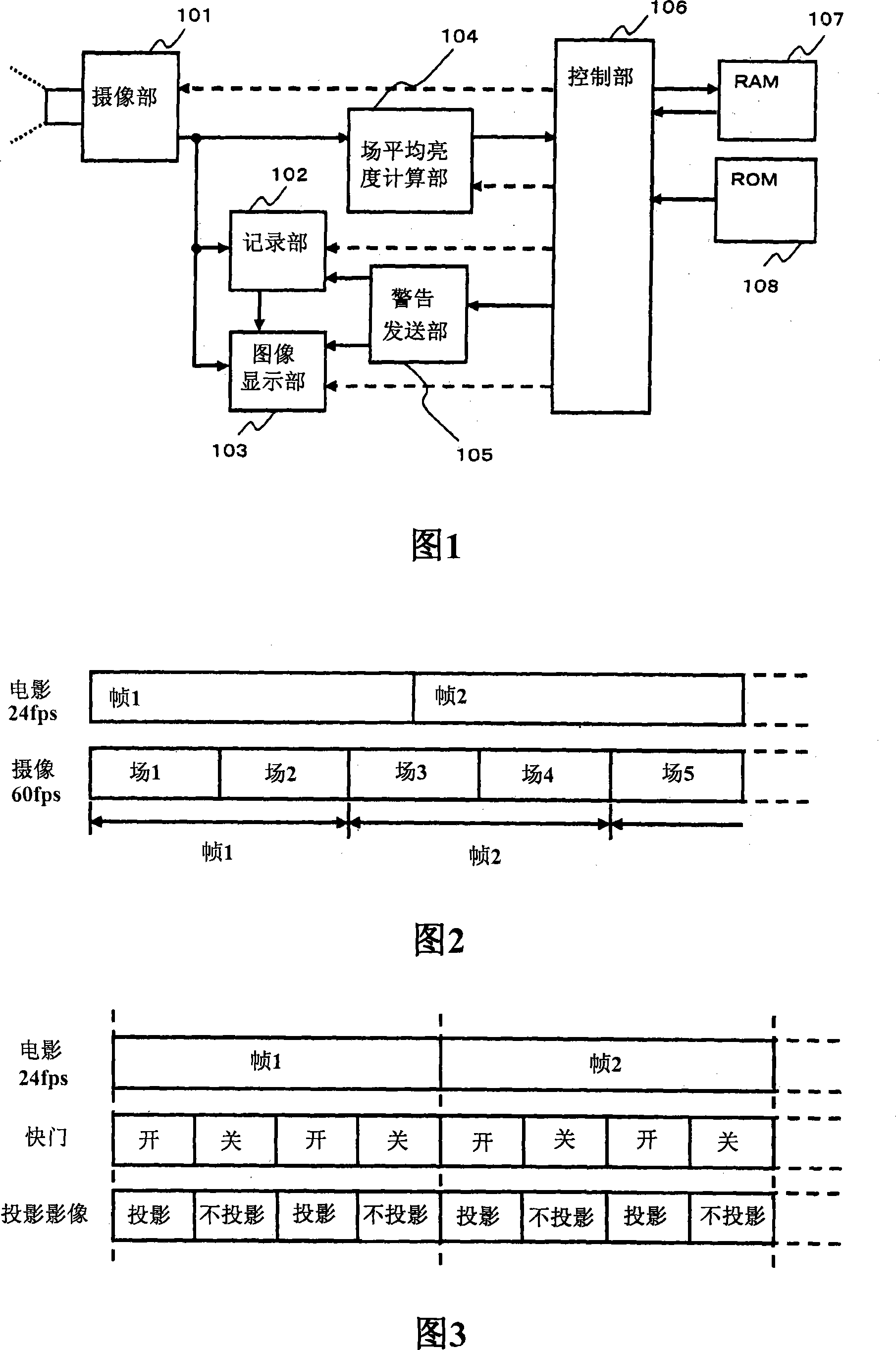
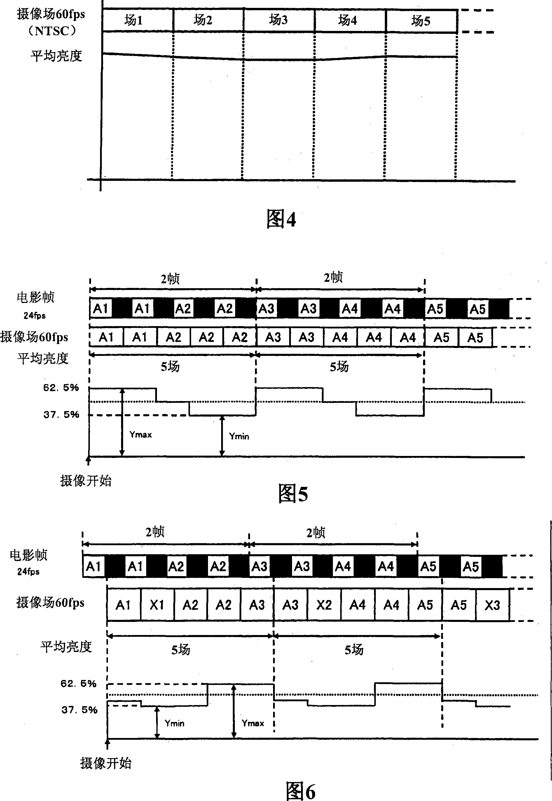
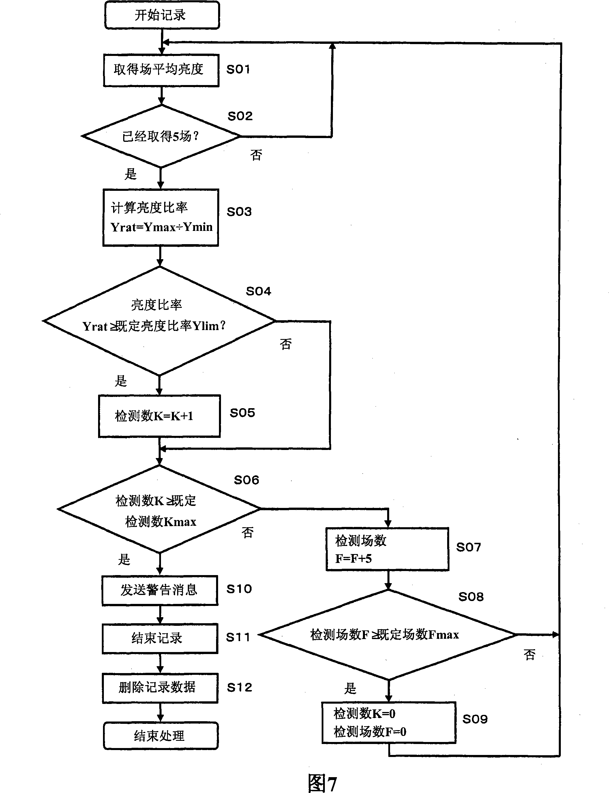
[0083] refer to figure 1 A configuration example of an imaging device applied to Embodiment 1 will be described. The imaging unit 101 converts a captured image into an electrical signal, and performs an optical function such as focusing a lens on a subject. The recording unit 102 writes the captured image on a recording medium such as a magnetic tape, HDD, magnetic disk, memory, or optical disk. Then, the recorded data is deleted according to an instruction from the control unit 106 . The image display unit 103 displays information necessary for shooting, such as time, when taking an image or capturing an image, and displays an image recorded in the recording unit 102 . The field average luminance calculation unit 104 calculates the average luminance of one field (field, field) of the captured image. The warning transmission unit 105 transmits a warning message to the recording unit 102 while displaying a warning message on the image display unit 103 when the control unit 1...
Embodiment 2
[0109] Then refer to Figure 8 A configuration example of an imaging device applied to the second embodiment will be described. The imaging unit 2101 converts a captured image into an electrical signal, and performs an optical function such as focusing a lens on a subject. The recording unit 2102 writes the captured image on a recording medium such as a magnetic tape, HDD, magnetic disk, memory, or optical disk. Furthermore, the recording unit 2102 deletes the recorded data according to an instruction from the control unit 2106 .
[0110] The image display unit 2103 displays information necessary for shooting, such as time, when capturing an image or capturing an image, and displays an image recorded in the recording unit 2102 . The average luminance calculation unit 2104 calculates the average luminance of the field of the captured image, and divides the field to calculate the average luminance. When the control unit 2106 detects a sneak shot of a movie, the warning transm...
Embodiment 3
[0142] Then refer to Figure 17 A configuration example of an imaging device applicable to Embodiment 3 will be described. The imaging unit 3101 converts an image captured by the imaging element 3101 a for imaging into an electrical signal, and also performs an optical function such as focusing a lens on a subject. In addition, it is constituted by a visible light luminance measuring element 3101b used for determination of sneak photography. The visible light luminance measuring element 3101b has a function of converting the luminance of imaging light entering through a lens into an electrical signal.
[0143] The recording unit 3102 writes captured images on a recording medium such as a magnetic tape, HDD, magnetic disk, memory, or optical disk. Then, the recorded data is deleted according to an instruction from the control unit 3106 .
[0144] The image display unit 3103 displays information necessary for shooting, such as time, when taking an image or capturing an image,...
PUM
 Abstract
Description
Claims
Application Information
 - R&D
- Intellectual Property
- Life Sciences
- Materials
- Tech Scout
- Unparalleled Data Quality
- Higher Quality Content
- 60% Fewer Hallucinations
Browse by: Latest US Patents, China's latest patents, Technical Efficacy Thesaurus, Application Domain, Technology Topic, Popular Technical Reports.
© 2025 PatSnap. All rights reserved.Legal|Privacy policy|Modern Slavery Act Transparency Statement|Sitemap|About US| Contact US: help@patsnap.com


