Sewing machine

A sewing machine, sewing needle technology, applied in the direction of sewing machine components, sewing equipment, ferrule mechanism for sewing machines, etc.

Inactive Publication Date: 2008-09-10
BROTHER KOGYO KK
View PDF0 Cites 12 Cited by
  • Summary
  • Abstract
  • Description
  • Claims
  • Application Information

AI Technical Summary

Problems solved by technology

Therefore, when the sewing direction at the beginning of sewing coincides with the holding direction of the upper thread end or the holding direction of the lower thread end, when the next sewing starts, there is a possibility that the sewing machine will be disengaged from the clamping body. The problem that the upper thread end and the lower thread end are sewn into the processed cloth

Method used


Image

  • Sewing machine
  • Sewing machine
  • Sewing machine

Examples


Embodiment Construction

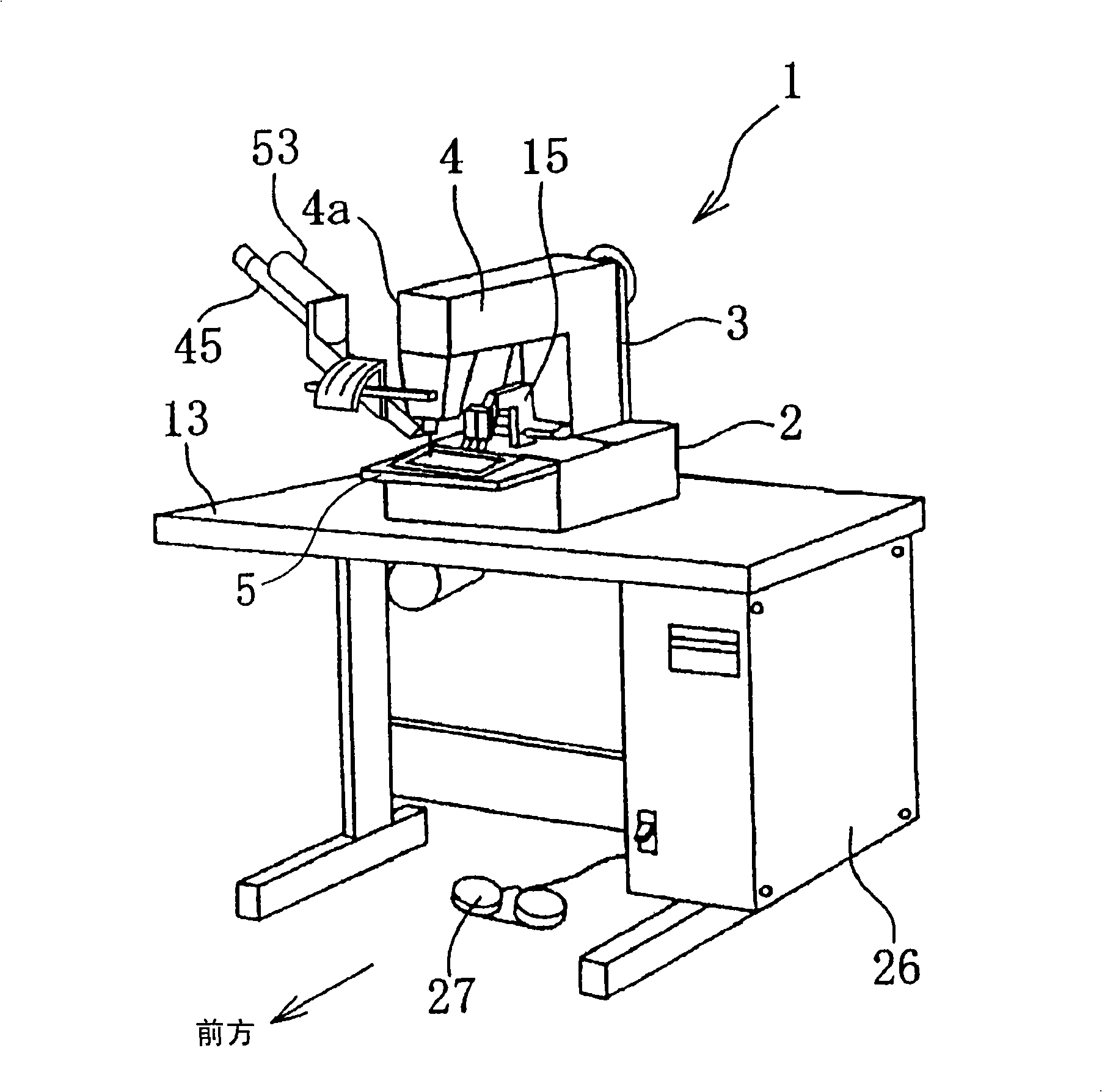
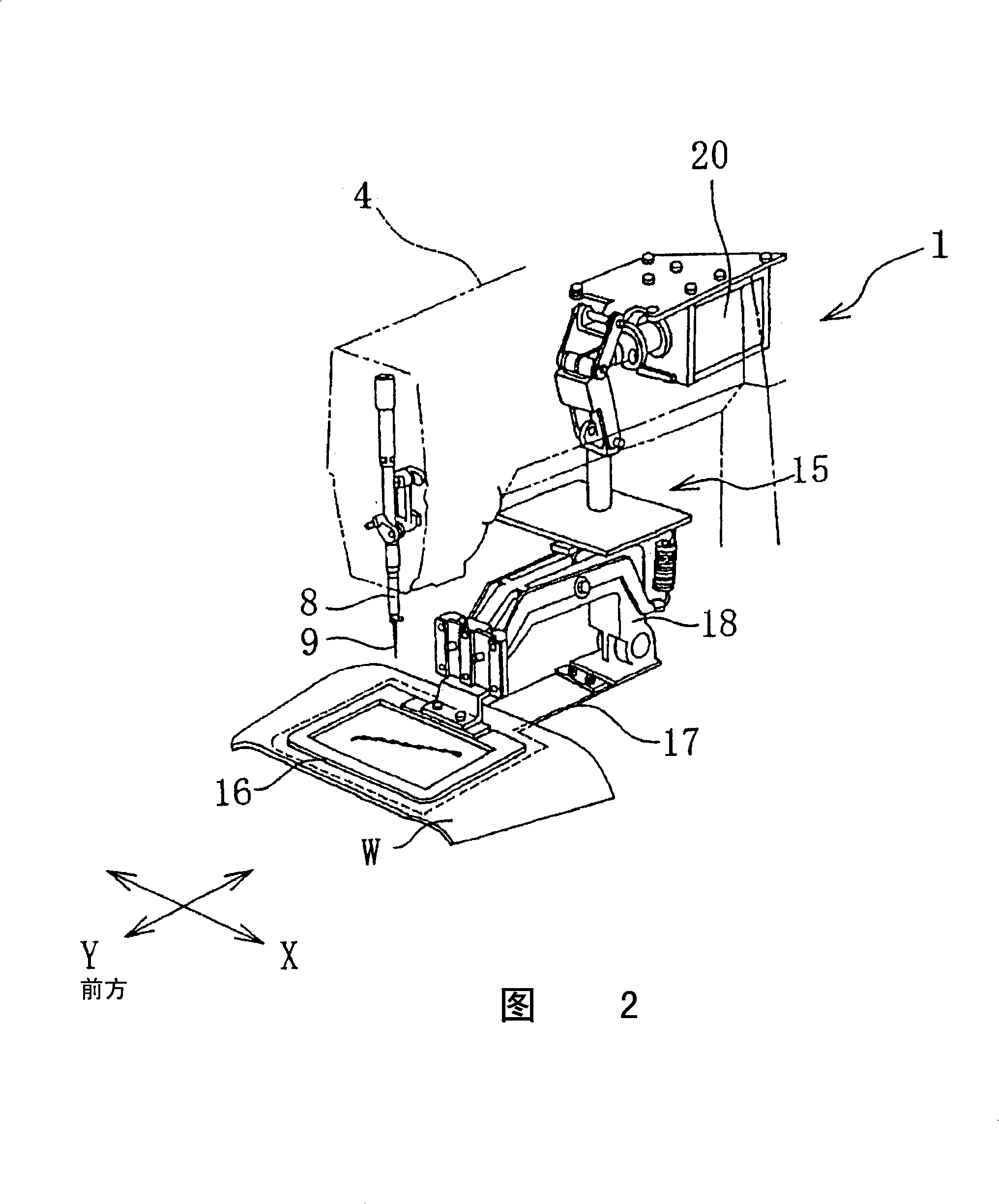
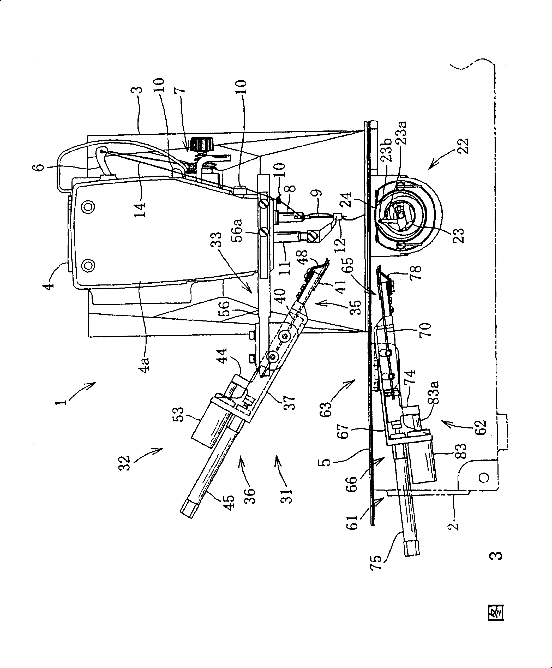
[0049] Such as figure 1 As shown, the sewing machine 1 has on the table 13: a bottom plate 2 as a sewing machine body, a column portion 3 continuous with the bottom plate 2 , and an arm portion 4 extending from the column 3 parallel to the bottom plate 2 . The bottom plate part 2 has a needle plate 5 and a cloth presser 15 on the upper part. The needle plate 5 has a needle hole 5a (refer to FIG. 5 ) through which the needle 9 can pass. The bottom plate portion 2, the column portion 3 and the machine arm portion 4 constitute a sewing machine frame. exist figure 1 In FIG. 1 , the side of the column portion 3 is defined as the rear of the sewing machine 1 , and the side of the clamp plate 16 described later is defined as the front of the sewing machine 1 .

[0050] The arm portion 4 has a main shaft (not shown) extending in the front-rear direction. A needle bar 8 and a thread take-up lever 6 that reciprocate up and down are provided on the machine arm 4 (see FIG. 3 ). A sew...


PUM


Abstract

The present invention relates to a sewing machine which can prevent the sewing of the end of the upper thread cut by an upper thread cutting mechanism that has a first movable blade. The sewing machine comprises the following components: an upper moving mechanism reciprocally moving the upper thread movable blade (40) between a first upper thread take-up position and a second upper thread take-up position by a predetermined distance, an upper thread holding mechanism holding an end of the upper thread (14) cut by the upper thread stretching to the needle hole of the sewing needle, and an upper thread direction adjusting mechanism located on the upper moving mechanism and the upper thread holding mechanism for adjusting a direction in which the upper thread stretching through the needle eye to the upper thread holding mechanism is drawn. The stretching direction of the upper thread is altered by the upper thread direction adjusting mechanism to lead to that the stretching direction of the upper thread in thread end holding state is different from the sewing direction when the sewing starts.

Description

technical field [0001] The present invention relates to a sewing machine including: an upper thread cutting mechanism for cutting an upper thread at the end of sewing; and an upper thread holding mechanism for holding the thread end cut by the upper thread cutting mechanism. Background technique [0002] Conventionally, there is a sewing machine provided with a thread cutting device for cutting the upper thread and the lower thread connected to the processed cloth. A conventional sewing machine has a thread holding mechanism for holding the thread ends of the upper thread and the lower thread cut by the thread cutting device. At the end of sewing, the thread cutting device cuts the upper and lower threads on the upper or lower side of the processed cloth automatically or according to the operator's thread cutting instructions. [0003] For example, the upper thread cutting device of the sewing machine described in Japanese Laid-Open Patent Publication Heisei 4th No. 26490 h...

Claims


Application Information

Patent Timeline
Patent Type & Authority Applications(China)
IPC IPC(8): D05B65/06D05B57/00
CPCD05B65/06D05B29/00D05B63/00D05B65/00D05B65/02
Inventor 早川範一中野元就
Owner BROTHER KOGYO KK
Why Eureka
Try Eureka