Sewing machine

A sewing machine and motor technology, which is applied to sewing machine components, sewing equipment, sewing machine control devices, etc., can solve the problems of not being able to fully realize the burden of workers, reduce the burden, and reduce the confusion of stitch formation, and suppress the confusion and burden. lightening effect

Active Publication Date: 2014-05-28
JUKI CORP
View PDF5 Cites 3 Cited by
  • Summary
  • Abstract
  • Description
  • Claims
  • Application Information

AI Technical Summary

Problems solved by technology

Therefore, there arises a problem that it is impossible to sufficiently reduce the burden on the operator during the lifting of the cloth presser foot.

Method used


Image

  • Sewing machine
  • Sewing machine
  • Sewing machine

Examples


Embodiment Construction

[0049] [Structure of Sewing Machine]

[0050] Next, a sewing machine 10 as an embodiment of the present invention will be described with reference to the drawings.

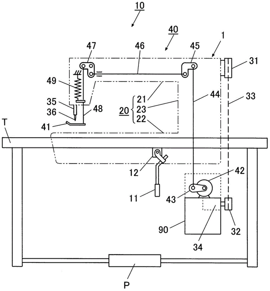
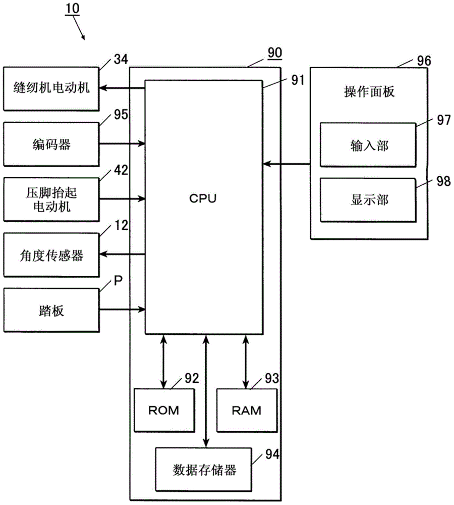
[0051] sewing machine 10 as figure 1 As shown, there are: a sewing machine main body 1, which is arranged on the sewing machine table T; a pedal P as a starting unit, which is arranged at the lower part of the sewing machine table T, and is used for starting the sewing machine motor described later and operating the rotation speed ; and the control unit 90, which centrally controls the various parts of the sewing machine.

[0052] Sewing machine body 1 such as figure 1 Shown is a sewing machine frame 20 having a substantially U-shaped outer shape when viewed from the side. This sewing machine frame 20 has: a sewing machine arm portion 21, which forms an upper portion of the sewing machine main body 1, extending in the left-right direction; a sewing machine base portion 22, which forms a lower portion of the sew...


PUM


Abstract

The invention provides a sewing machine which reduces operation load of an operating lever and prevents misoperation of a cloth presser foot. The sewing machine includes a sewing machine motor, a cloth presser foot, a presser foot lifting motor which applies a lifting motion to the cloth presser foot, an operating lever, through which an operator performs instruction input to the lifting motion of the cloth presser foot, a detection unit which detects an occurrence of changes in a pendulum angle of the operating lever, and a control unit which controls the motion that the presser foot lifts up the motor. In the sewing machine, the control part, during the stop of the sewing machine motor and when the changes in the pendulum angle of the operating lever is detected by the detection unit, utilizes the presser foot lifting motor to elevate the cloth presser foot to a cloth releasing height, and during the motion of the sewing machine motor and when the changes in the pendulum angle of the operating lever is detected by the detection unit, prohibits the lifting action of the cloth presser foot realized by the presser foot lifting motor, or enables the cloth presser foot to be elevated to a limited height which requires little lifting motion amount than the cloth releasing height.

Description

technical field [0001] The invention relates to a sewing machine with a presser foot lifting device. Background technique [0002] A conventional sewing machine has a structure in which an operator applies force to a knee lever mounted on a table mounted on the sewing machine, thereby raising a cloth presser for holding a sewing object. [0003] However, since the knee lever is operated against the spring that applies a cloth holding pressure to the cloth presser foot to raise the cloth presser foot, repeated lifting and lowering of the cloth presser foot will impose a burden on the operator. [0004] Therefore, in recent years, a sewing machine equipped with an actuator for giving a lifting motion to a cloth presser foot has been proposed (for example, refer to Patent Document 1). [0005] In the case of the above-mentioned sewing machine, if the knee switch detects an instruction input of the lifting operation of the presser foot applied to the knee lever, the actuator ra...

Claims


Application Information

Patent Timeline
Patent Type & Authority Applications(China)
IPC IPC(8): D05B69/00
CPCD05B29/02D05B69/30D05D2205/32D05D2305/36
Inventor 伊藤文夫
Owner JUKI CORP
Why Eureka
Try Eureka