
Control method of sewing machine

A control method and technology for sewing machines, which can be applied to control devices for sewing machines, sewing machine components, sewing machines, etc., can solve problems such as cost

Active Publication Date: 2018-02-13
JUKI CORP
View PDF10 Cites 0 Cited by
  • Summary
  • Abstract
  • Description
  • Claims
  • Application Information

AI Technical Summary

Problems solved by technology

[0006] However, in the above-mentioned sewing machine, since the thread puller 124 with a complicated structure is provided on the upstream side of the thread take-up lever 118, there is a problem of cost due to an increase in the number of parts.

Method used


Image

  • Control method of sewing machine
  • Control method of sewing machine
  • Control method of sewing machine

Examples


Embodiment Construction

[0045] Next, an embodiment of the control method of the present invention will be described using a sewing machine capable of realizing the control method of the sewing machine.

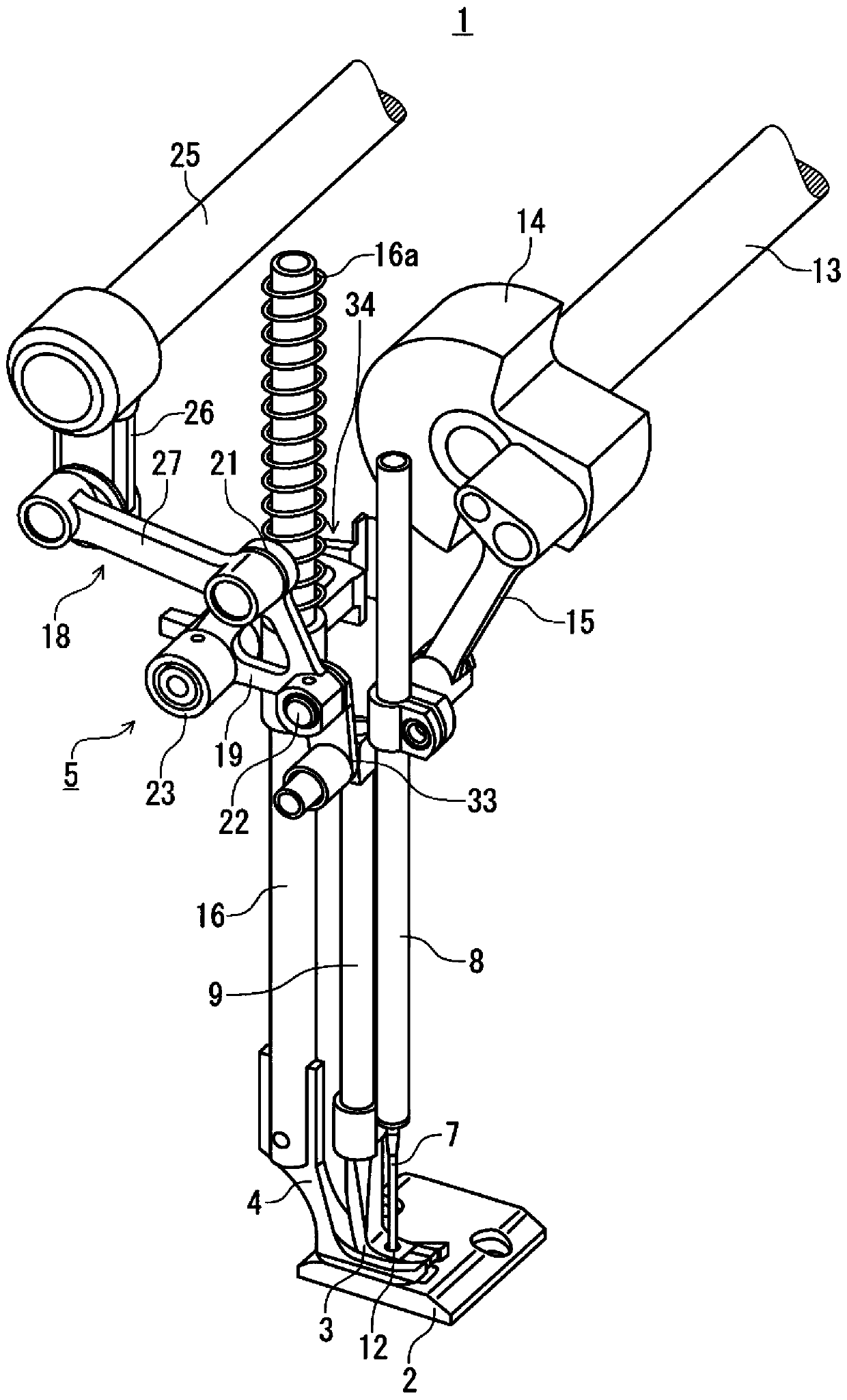
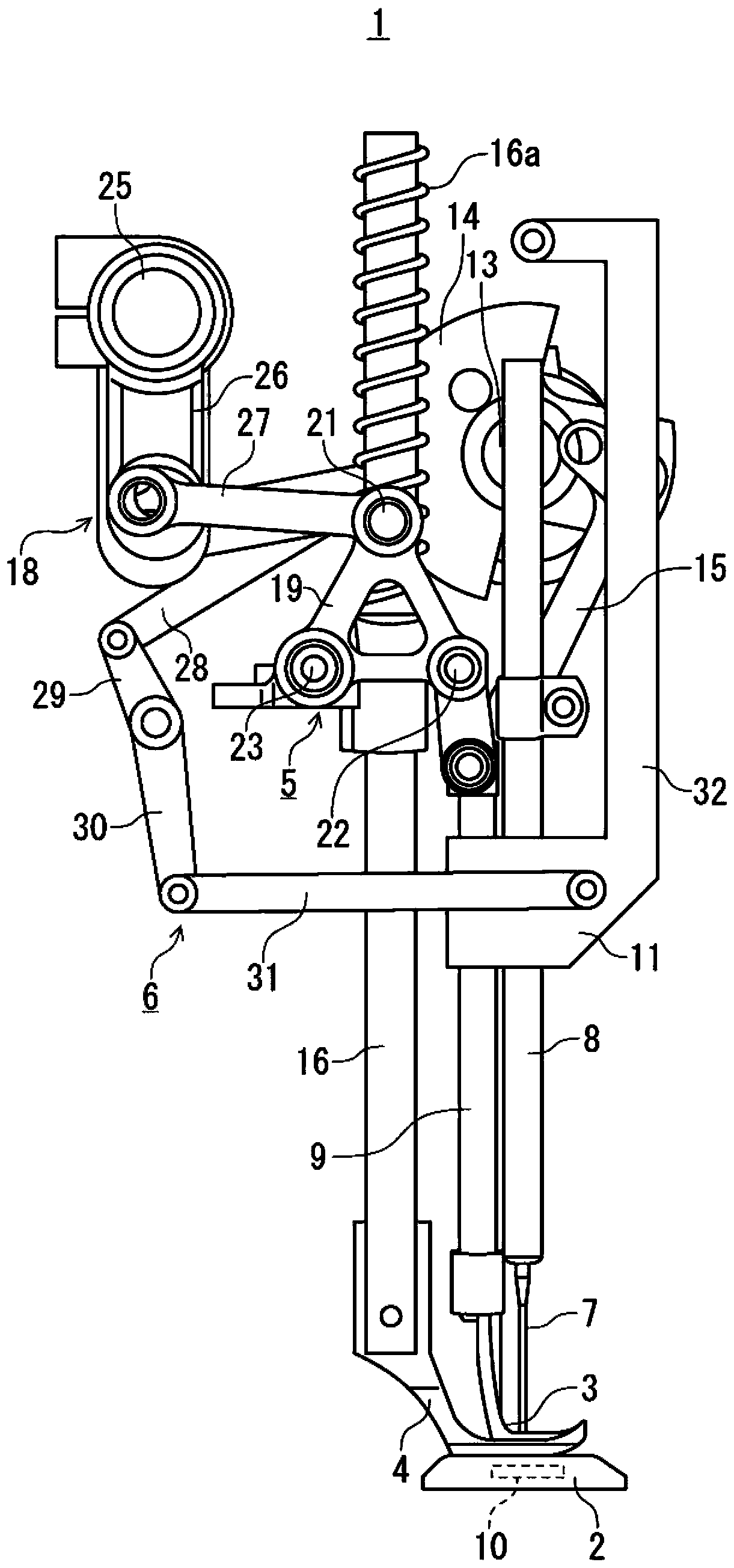
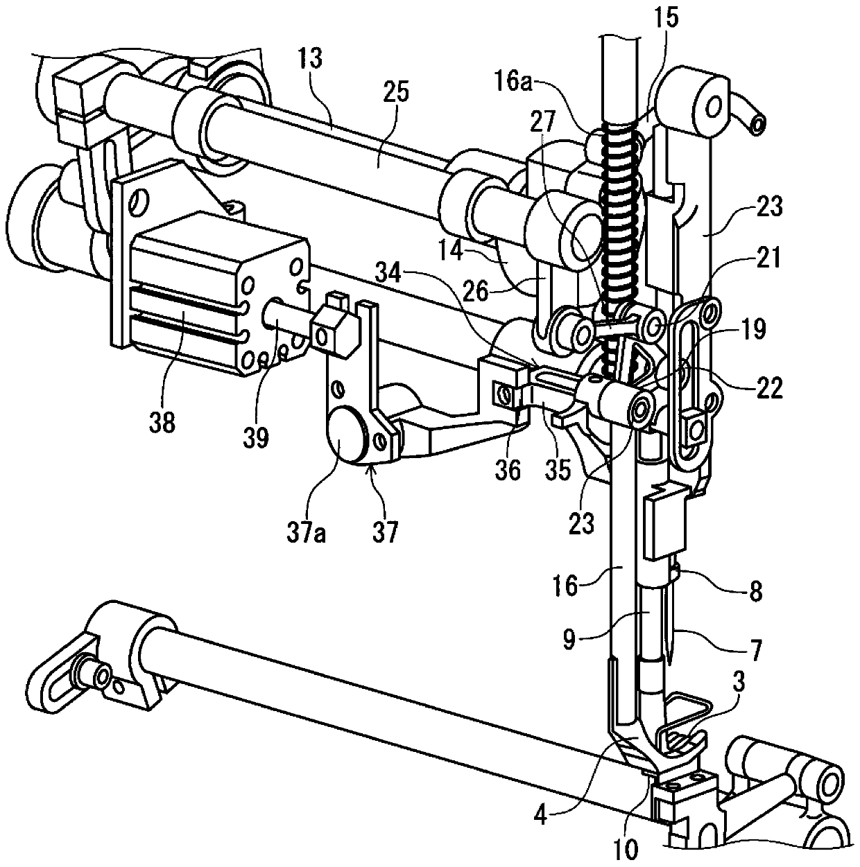
[0046] Such as Figure 1 ~ Figure 3 As shown, the sewing machine 1 has: an upper feed foot 3, which moves in a predetermined direction, that is, the feed direction of the sewn object W, in a state of contacting the object to be sewn W on the needle plate 2 from above to feed the object to be sewn. The sewing product W is conveyed; the presser foot 4 presses the sewing product W toward the needle plate 2 from above; the first action mechanism 5 makes the upper feed foot 3 and the presser foot 4 move up and down in opposite phases. and the second action mechanism 6, which makes the upper feed foot 3 reciprocate in the horizontal direction (feed direction).

[0047] The upper feed leg 3 is supported by a support bar 9 extending in the up and down direction so as to be in the length direction of the nee...


PUM


Abstract

The present invention provides a control method of a sewing machine capable of preventing the second stitch and the upper thread end from the second stitch from being sewn in while suppressing an increase in cost, thereby enabling good sewing. This sewing machine has: a needle bar for holding and raising and lowering the needle with the upper thread inserted into the needle hole, thereby inserting the needle into the object to be sewn so that the upper thread passes through the back side of the object to be sewn; , which is set under the object to be sewn, swings through the linkage with the lifting action of the needle bar, so that the tip catches the upper thread passing through the back side of the object to be sewn; The upper thread is held on the upper thread path between the needles, and the movement of the upper thread is restricted; and the control part drives the holding device after the tip of the kettle catches the upper thread in the second stitch of the sewing object to be sewn, thereby limiting Mobile on the line.

Description

technical field [0001] The present invention relates to a control method of a sewing machine that sews on a sewn object such as cloth. Background technique [0002] In the existing sewing machine, there is the following problem: when sewing on the object to be sewn, the upper thread is pulled into the back side of the object to be sewn in the first stitch at the beginning of sewing, and remains on the surface of the object to be sewn. The end of the upper thread on the back side of the sewn product becomes long, making the product unsightly in appearance. In order to solve this problem, there is known a sewing machine provided with a thread pulling device that shortens an upper thread pulled into the back side of a sewing object at the start of sewing (for example, refer to Patent Document 1). [0003] Such as Figure 8 Shown, this sewing machine has needle bar 107, and this needle bar 107 has the sewing needle 108 that guides upper thread 109 in the mode of penetrating to ...

Claims


Application Information

Patent Timeline
Patent Type & Authority Patents(China)
IPC IPC(8): D05B69/20
Inventor 矢萩智雄
Owner JUKI CORP
Learn More