Pendulum shaft gyroscope coupled stepless speed changer

A continuously variable transmission, gyro technology, applied in the direction of friction transmission, belt/chain/gear, mechanical equipment, etc., can solve problems such as low efficiency, and achieve the effect of saving shifting

Inactive Publication Date: 2008-09-10
李维农
View PDF0 Cites 1 Cited by
  • Summary
  • Abstract
  • Description
  • Claims
  • Application Information

AI Technical Summary

Problems solved by technology

The above three types are all non-rigid connections, which essentially use friction, so the efficiency is low

Method used


Image

  • Pendulum shaft gyroscope coupled stepless speed changer
  • Pendulum shaft gyroscope coupled stepless speed changer
  • Pendulum shaft gyroscope coupled stepless speed changer

Examples


Embodiment Construction

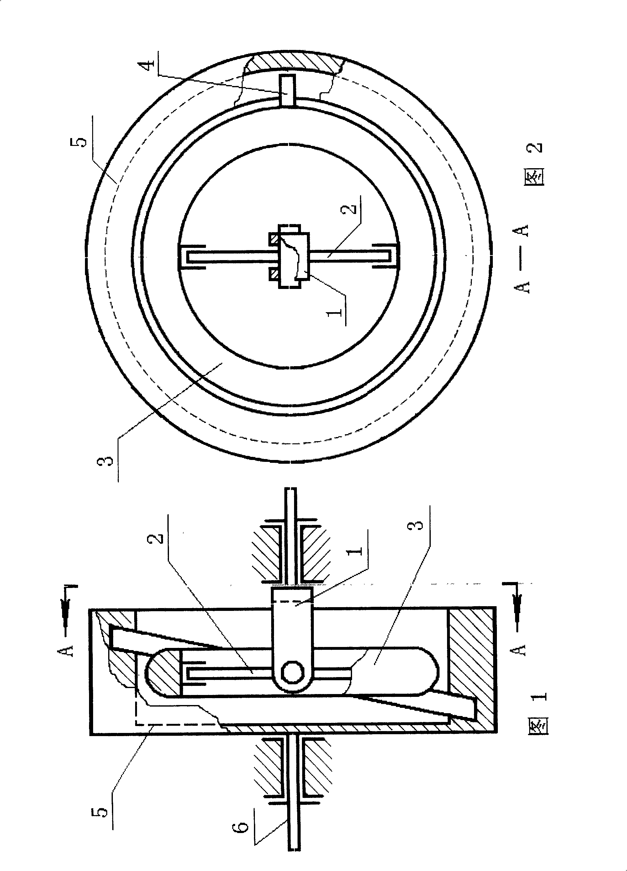
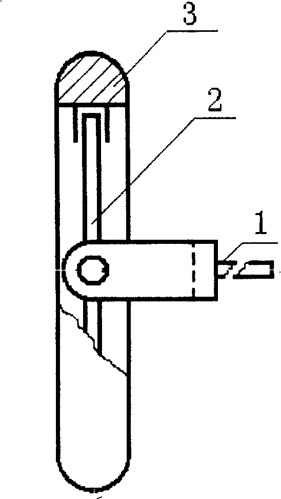
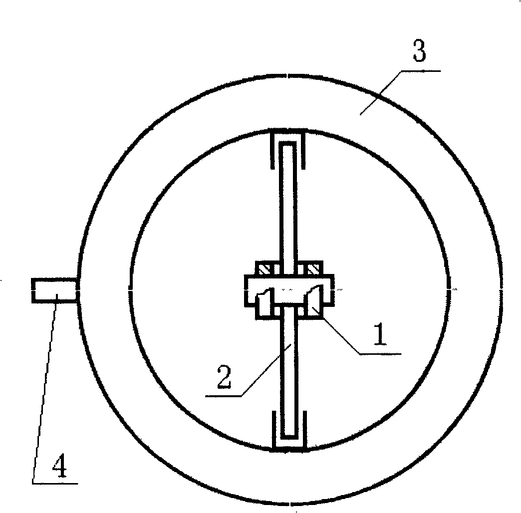
[0016] Embodiments of the present invention are shown in the accompanying drawings, in which 1 is an input shaft, 2 is a cross shaft, 3 is a top, 4 is a top balance shaft, 5 is a cam, and 6 is an output shaft. The input shaft 1 forms a universal connection with the top 3 through the cross shaft 2, and then connects with the cam 5 integrated with the output shaft 6 through the swing shaft 4 of the top. The rotational power input from the input shaft 1 makes the gyro 3 obtain kinetic energy and rotate through the universal connection, and the gyro effect is generated due to the restriction of the steering of the gyro 3 by the cam 5 through the gyro pendulum shaft 4, so that the gyro 3 generates self-rotation and corresponding Precession and nutation, due to the gyro effect through the dynamic action of the gyro pendulum shaft 4 on the cam 5, the power coupling between the gyro 3 and the cam 5 is realized, and then the output shaft 6 connected to the cam 5 generates a rotational t...


PUM


Abstract

The invention discloses a pendulum shaft whirligig coupled continuously variable transmission, belonging to the mechanical continuously variable transmission field. The transmission consists of an input shaft, a universal joint slack, a whirligig, a pendulum shaft of the whirligig, a cam and an output shaft, etc. The input shaft is connected with the whirligig through the universal joint slack, and is connected with the cam which is integrated with the output shaft, through the pendulum shaft of the whirligig. The rotative power inputted from the input shaft enables the whirligig by the universal joint slack to obtain kinetic energy so as to rotate, and the cam enables the whirligig to carry out autogiration, corresponding precesional motion and nutation by the gyroscopic effect generated by the constraint of the pendulum shaft of the whirligig upon the turning of the whirligig. Since the gyroscopic effect dynamically functions upon the cam through the pendulum shaft of the whirligig, power coupling is realized between the whirligig and the cam. And then the output shaft connected with the cam generates driving moment, so that power flow with variable speed ratio is formed between the input shaft and the output shaft, and the continuously variable transmission is realized.

Description

technical field [0001] The invention belongs to the field of mechanical stepless transmissions. Background technique [0002] In the field of mechanical continuously variable transmissions, there are currently three categories: namely (1) hydraulic type; (2) electromagnetic type; (3) friction type. The above three types are non-rigidly connected, and essentially use friction, so the efficiency is low. Contents of the invention [0003] The object of the present invention is to design a pendulum gyro-coupled continuously variable transmission that can overcome the above disadvantages and realize rigid connection, so as to realize the long-awaited goal of people in the field of mechanical transmission. [0004] The invention discloses a pendulum shaft gyro coupled continuously variable transmission, which is composed of an input shaft, a universal coupling, a top, a gyro pendulum shaft, a cam, an output shaft, etc., and the input shaft is connected with the gyro through the...

Claims


Application Information

Patent Timeline
Patent Type & Authority Applications(China)
IPC IPC(8): F16H15/04F16H35/00F16H37/00
Inventor 李维农
Owner 李维农
Why Eureka
Try Eureka