Information output device, medium, and information input/output device

An information output and media technology, applied in the field of card game machines, can solve the problems of increasing the size of the device, difficult to set up the game machine, and unable to accurately read the information changes.

Inactive Publication Date: 2008-09-10
YOSHIDA KENJI (I) (JP)
View PDF2 Cites 15 Cited by
  • Summary
  • Abstract
  • Description
  • Claims
  • Application Information

AI Technical Summary

Problems solved by technology

[0004] However, the game machine shown in Japanese Laid-Open Patent No. JP2005-46649A only provides a camera (camera) in the casing of the game machine, so it is impossible to accurately read changes in information (such as the direction of the card, coordinates or different codes). value, etc.)
[0005] In addition, the game machine shown in Japanese Laid-Open Patent No. JP2002-102529A provides a columnar support in the casing of the game machine, while the cards are located on the platform, and a display device (such as a projector) is located on the columnar support. support, resulting in increased device size
Therefore, cause described game machine to be difficult to be arranged in amusement park

Method used


Image

  • Information output device, medium, and information input/output device
  • Information output device, medium, and information input/output device
  • Information output device, medium, and information input/output device

Examples


no. 1 example -

[0207] First Embodiment - Multi-Sensor Game Machine

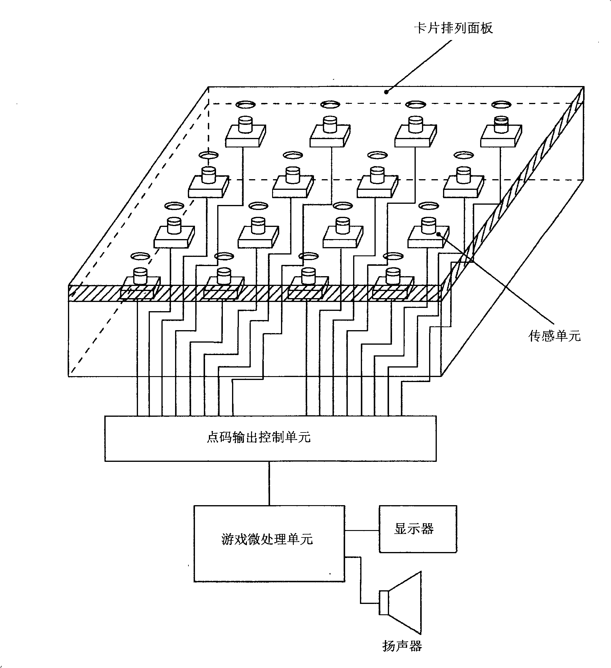
[0208] Such as Figure 1 to Figure 8 As shown, it discloses the card game machine of the first embodiment of the present invention.

[0209] Such as figure 1 , which reveals a front view of the appearance of a card game machine provided with several sensors.

[0210]The card game machine includes a card arrangement panel so that cards held by a player are arranged on the card arrangement panel. The card alignment panel has 16 reading holes for the sensors of the sensing unit (described in detail below) to emit light. Furthermore, the card arrangement panel further includes: a display for displaying the progress of the game; and a speaker for outputting music or sound.

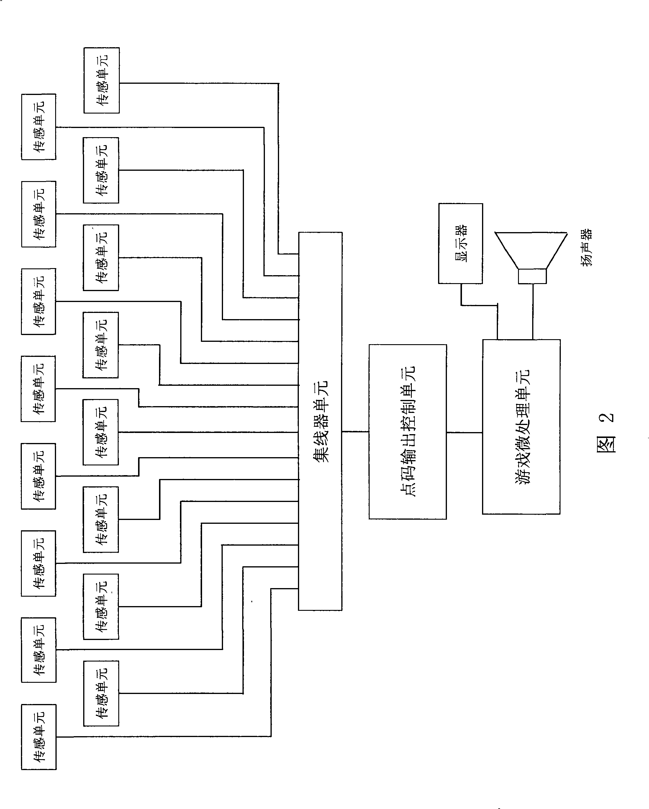
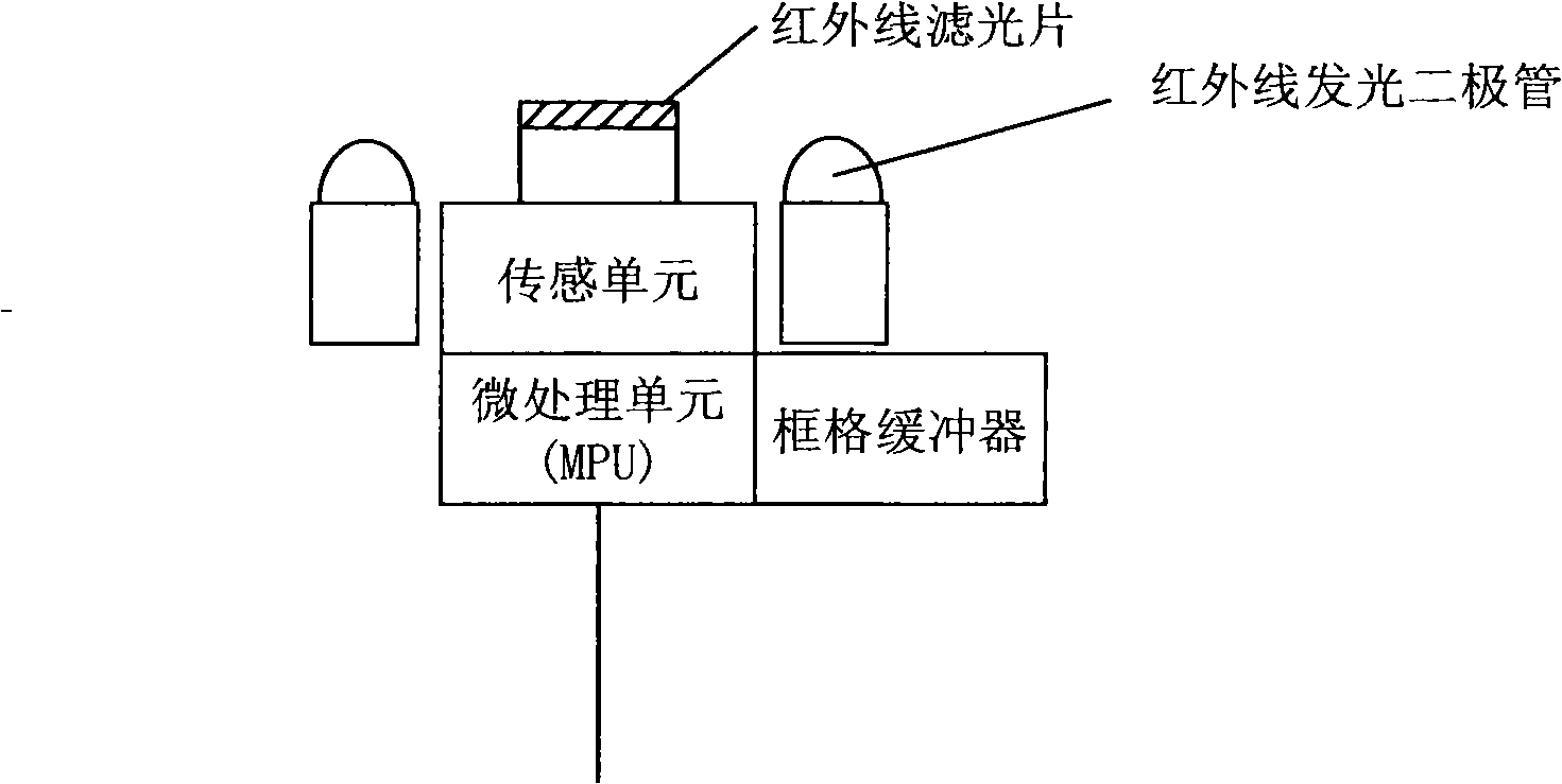
[0211] Furthermore, the card game machine is provided with 16 sensing units. The sensing unit is connected to the dot code output control unit via a local area network (LAN) or a hub (Hub) unit (described in detail below). Furthermore, the point code ...

no. 2 example -

[0240] Second Embodiment - Single Sensor Game Machine

[0241] Such as Figure 9 to Figure 3 9, which discloses the card game machine of the second embodiment of the present invention.

[0242] Such as Figure 9 , which reveals the perspective view of the appearance of the card game machine, and as Figure 10A and Figure 10B As shown in , it discloses a longitudinal sectional view of the card game machine.

[0243] In the card game machine of this embodiment, the entire bottom surface of the card arrangement panel is photographed by a single sensor (image unit).

[0244]In the space (the space below the platform) of the bottom surface of the card arrangement panel, there are several positions to prevent the image light emitted by the sensing unit (image unit) from hitting the panel surface (the bottom surface of the platform) ); a number of infrared light emitting diodes (IRLEDs, i.e. emitting light sources) for emitting illuminating light to the dot pattern on the card ...

Embodiment

[0375] Example - Changing Infrared Characteristics

[0376] Such as Figure 54 to Figure 68 As shown, it discloses that in an embodiment of the present invention, at least two systems of several dot patterns are composed of at least two inks with different reactivity, which are printed on a medium for selective or repetitive reading. A system of at least one of the dot patterns among at least two systems of the dot patterns is taken.

[0377] Such as Figure 54 As shown in FIG. 1 , it discloses a graph between dot patterns formed by two inks with different infrared absorptivity in an embodiment of the present invention. The difference in the infrared absorption rate can be caused by controlling the carbon content contained in the ink.

[0378] Such as Figure 54 As shown, it discloses at least two inks with different reactivity according to an embodiment of the present invention, and the at least two inks have different infrared absorption rates in all frequency bands (ie,...


PUM


Abstract

The invention provides an information output device in which information of a medium disposed on a stage surface can be surely and efficiently read out, and a stage effect and a security are high. In the information output device, media are disposed on a stage surface in a state where the media are opposite to the stage surface, the media where dot patterns are printed on medium surfaces on the basis of a predetermined rule, the dot patterns are read by imaging units disposed in a space below the stage and converted into code values or coordinate values indicating the dot patterns from photographed images obtained by the imaging units, and information corresponding to the code values or the coordinate values is outputted. Further, light transmitting reading holes are respectively provided at a plurality of medium disposing locations on the stage surface, and the imaging units are disposed in the space below the stage corresponding the respective reading holes such that the imaging units photograph the medium surfaces of the media disposed on the reading holes.

Description

technical field [0001] The invention relates to a card game machine. Background technique [0002] In general, card game machines in which cards are placed on the platform of the game machine to execute the card game are very popular for commercial game machines installed in places such as amusement parks or for game machines connected to home TV screens (For example, as shown in Japanese Laid-Open Patent No. JP2005-46649A). [0003] Furthermore, in the game machine, information about the game (such as the value of the cards on the platform generated by the player or the result of the game) is usually displayed as an image on the platform by using a projector (for example, Japanese Patent Publication No. JP2002-102529A). [0004] However, the game machine shown in Japanese Laid-Open Patent No. JP2005-46649A only provides a camera (camera) in the casing of the game machine, so it is impossible to accurately read changes in information (such as the direction of the card, coo...

Claims


Application Information

Patent Timeline
IPC IPC(8): G06F3/042A63F13/00A63F13/08A63F1/00A63F1/02A63F3/02H04N1/195G06K19/06G06K19/08A63F13/213A63F13/26A63F13/428
Inventor 吉田健治
Owner YOSHIDA KENJI (I) (JP)
Why Eureka
Try Eureka