

Flood chamber for coating installations
A perfusion chamber and perfusion technology, applied in the field of perfusion chambers, can solve problems such as short perfusion time, and achieve the effect of offsetting the swing
- Summary
- Abstract
- Description
- Claims
- Application Information
AI Technical Summary
Benefits of technology
Problems solved by technology
Method used
Image

Examples
Embodiment Construction
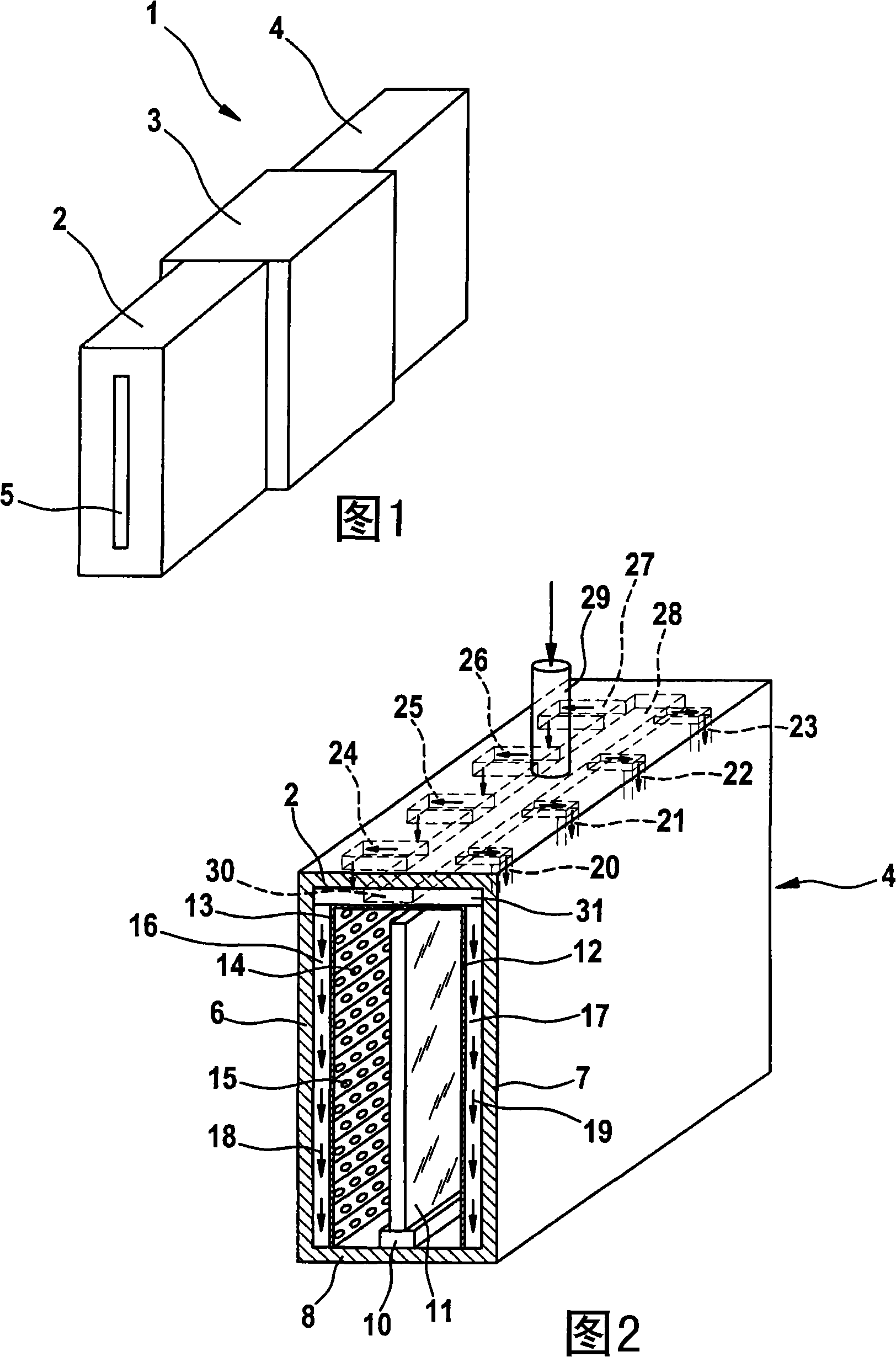
[0040] FIG. 1 shows a schematic diagram of an in-line coating plant 1 with an inlet chamber 2 , a treatment chamber 3 and an outlet chamber 4 . The surface substrate to be coated (for example a glass plate) is introduced through the opening 5 of the feed chamber 2 and transported to the treatment chamber 3, where the substrate is coated. After coating, the substrate reaches the discharge chamber 4 and from there is transported to the outside.
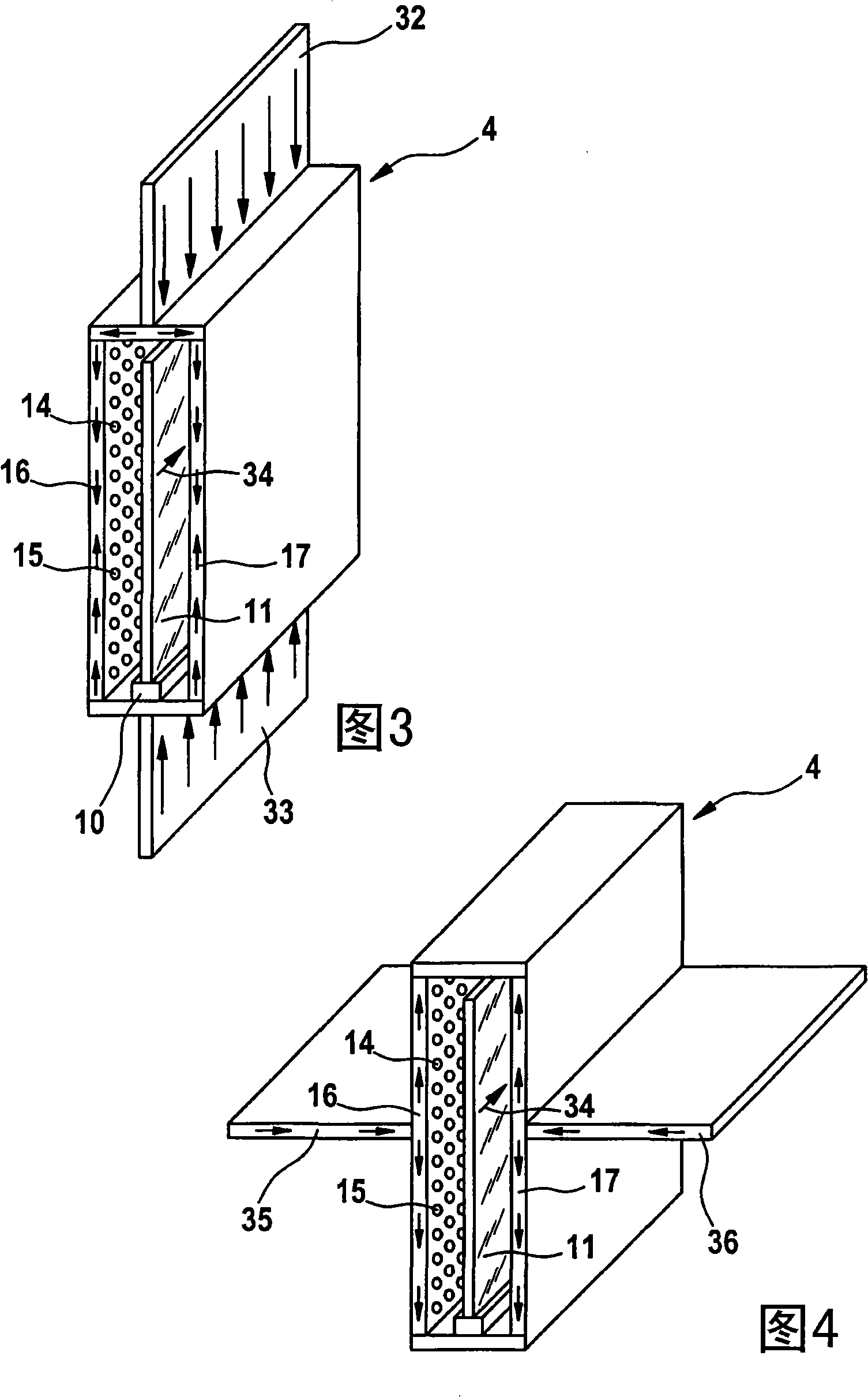
[0041] FIG. 2 again shows the tap chamber 4 isolated. The four lock chamber walls 6 to 9 and the transport device 10 for the substrate 11 (here a glass plate) can be seen. The perfusion walls are indicated with 12 and 13 and provided with holes 14,15. The perfusion walls 12 , 13 together with the interior of the locking chamber walls 6 , 7 form perfusion channels 16 , 17 through which gas flows and subsequently through the holes 14 , 15 . The gas flow is indicated by arrows 18 , 19 . Feed via a gas supply pipe 29 , the gas supply ta...
PUM
 Abstract
Description
Claims
Application Information