
Flood chamber for coating installations

A perfusion chamber and perfusion technology, which is applied in the field of perfusion chambers, can solve problems such as short perfusion time, and achieve the effect of offsetting the swing

Active Publication Date: 2013-01-23
APPLIED MATERIALS INC
View PDF5 Cites 0 Cited by
  • Summary
  • Abstract
  • Description
  • Claims
  • Application Information

AI Technical Summary

Problems solved by technology

[0025] The present invention addresses the problem of reducing the cycle time to a shorter perfusion time

Method used


Image

  • Flood chamber for coating installations
  • Flood chamber for coating installations
  • Flood chamber for coating installations

Examples


Embodiment Construction

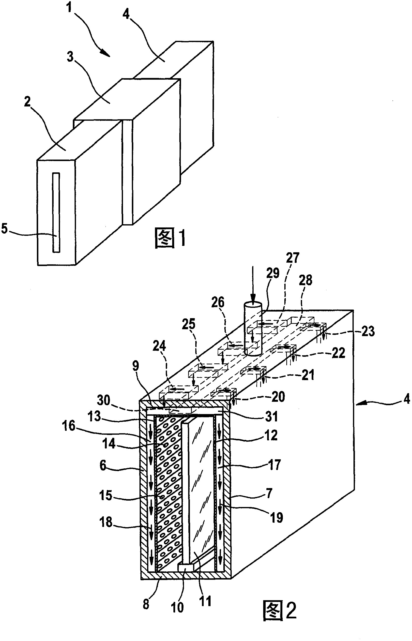
[0042] FIG. 1 shows a schematic diagram of an in-line coating plant 1 with an inlet chamber 2 , a treatment chamber 3 and an outlet chamber 4 . The surface substrate to be coated (for example a glass plate) is introduced through the opening 5 of the feed chamber 2 and transported to the treatment chamber 3, where the substrate is coated. After coating, the substrate reaches the discharge chamber 4 and from there is transported to the outside.

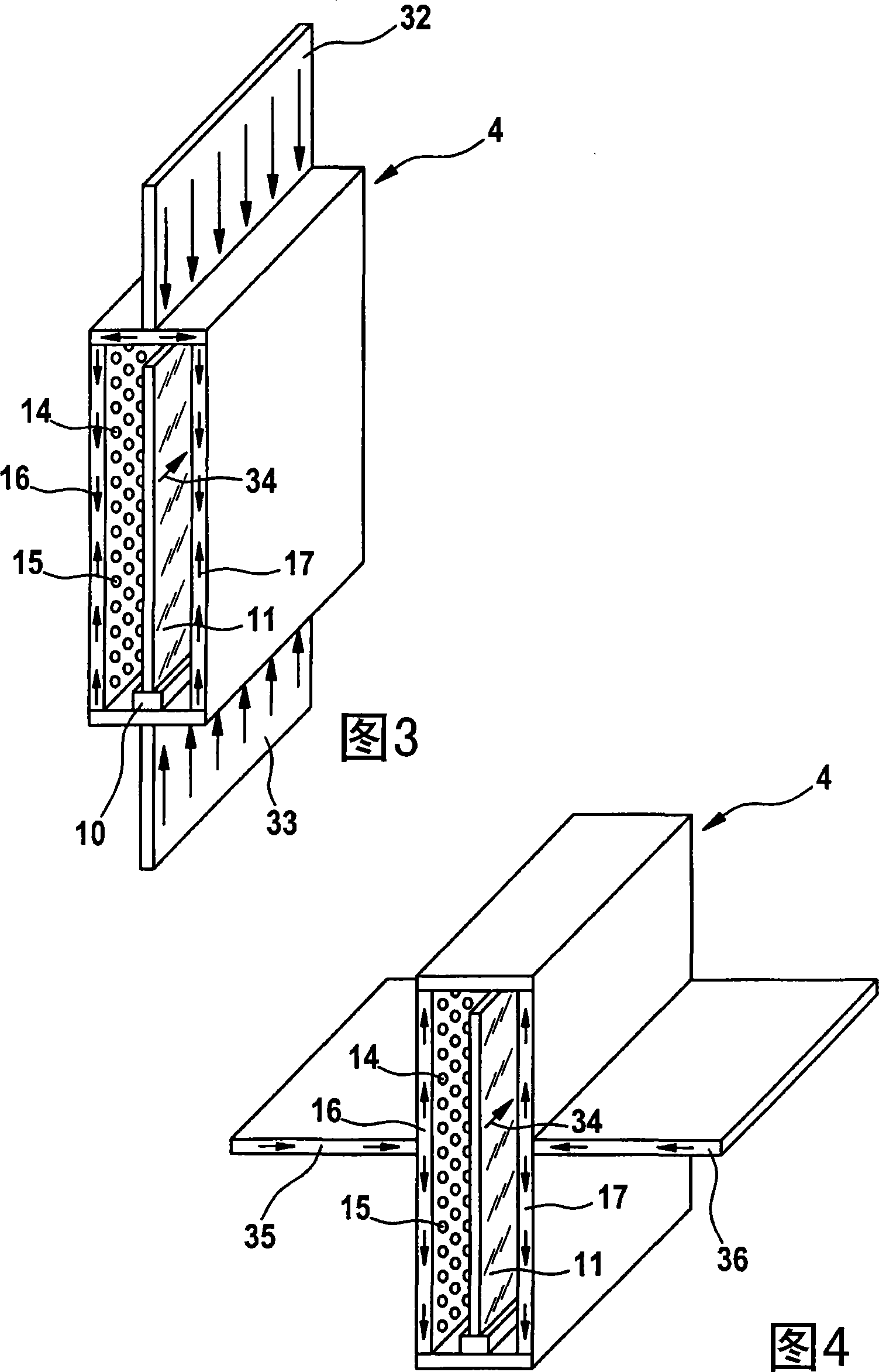
[0043] FIG. 2 again shows the tap chamber 4 isolated. The four lock chamber walls 6 to 9 and the transport device 10 for the substrate 11 (here a glass plate) can be seen. The perfusion walls are indicated with 12 and 13 and provided with holes 14,15. The perfusion walls 12 , 13 together with the interior of the locking chamber walls 6 , 7 form perfusion channels 16 , 17 through which gas flows and subsequently through the holes 14 , 15 . The gas flow is indicated by arrows 18 , 19 . Feed via a gas supply pipe 29 , the gas supply ta...


PUM


Abstract

The chamber has two flooding units comprising flooding walls that include a set of fluid penetration openings. One flooding unit is arranged on one side of a plane substrate and the other flooding unit is arranged on the other side of the plane substrate. The flooding units are connected to a fluid source at a given fluid pressure. A portion of the fluid penetration openings is directed toward a substrate (11).

Description

technical field [0001] The invention relates to a flooding chamber for a coating apparatus in which planar substrates are coated. Background technique [0002] In high vacuum coating equipment, the feed and discharge lock chambers are usually arranged in front or behind the high vacuum coating chamber, respectively. The substrates to be coated, eg glass plates, are guided through these infeed and outfeed chambers, so that the entire high vacuum coating chamber with each individual substrate does not have to be re-evacuated. The feed chamber has the function of transferring the substrate from the region of atmospheric pressure into the region of vacuum, while the discharge chamber has the task of transferring the currently coated substrate from the region of vacuum into the region of atmospheric pressure. [0003] For example, FIG. 1 of DE 10 2004 008 598 A1 discloses a coating device with an inlet chamber, a treatment chamber and an outlet chamber. Between the feeding cham...

Claims


Application Information

Patent Timeline
Patent Type & Authority Patents(China)
IPC IPC(8): C23C14/56
CPCH01L21/6715C03C2218/114C03C17/002H01L21/00H01L21/02H01L21/08
Inventor 托马斯·格贝尔安德里亚斯·鲁普奥利弗·海梅尔
Owner APPLIED MATERIALS INC
Learn More