Rigidizable inflating-expansion radial direction rib support type offset-feed paraboloidal antenna

A parabolic antenna, inflatable deployment technology, applied to antennas, electrical components, etc., can solve the problems of low deployment reliability, complex driving mechanism, and high cost, and achieve the effects of high deployment reliability, reduced folding volume, and high strength.

Inactive Publication Date: 2008-10-01
HARBIN INST OF TECH
View PDF0 Cites 28 Cited by
  • Summary
  • Abstract
  • Description
  • Claims
  • Application Information

AI Technical Summary

Problems solved by technology

[0003] The purpose of the present invention is to solve the problem that the existing satellite antennas are mostly mechanical structures. The satellite antennas with this mechanical structure have low unfol

Method used


Image

  • Rigidizable inflating-expansion radial direction rib support type offset-feed paraboloidal antenna
  • Rigidizable inflating-expansion radial direction rib support type offset-feed paraboloidal antenna
  • Rigidizable inflating-expansion radial direction rib support type offset-feed paraboloidal antenna

Examples


specific Embodiment approach 1

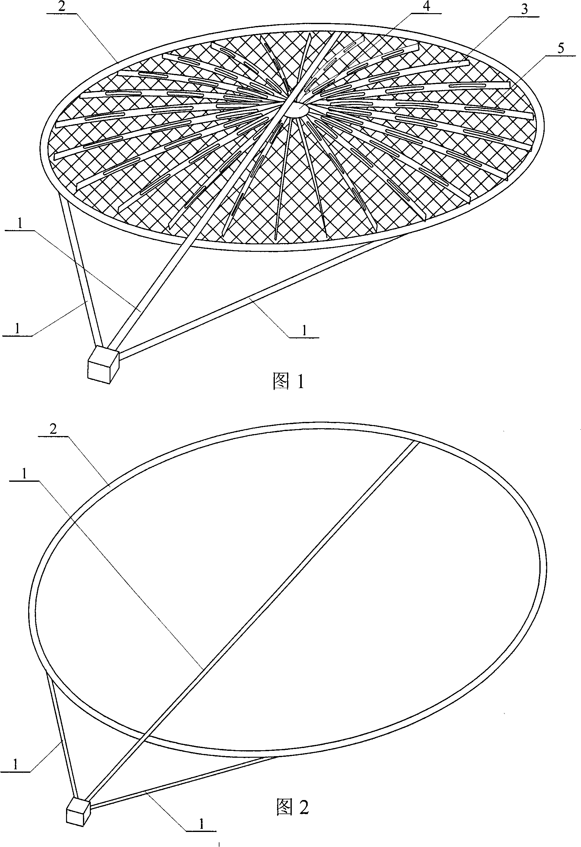
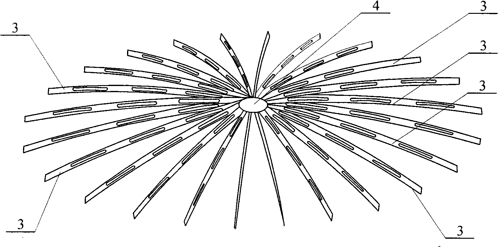
[0007] Embodiment 1: (see Figures 1 to 5) this embodiment consists of three inflatable support tubes 1, inflatable support rings 2, multiple radial ribs 3, a central drum 4, an elastic reflecting surface mesh 5 and a suspension wire 6 A plurality of radial ribs 3 are arranged radially, one end of the plurality of radial ribs 3 is connected with the central drum 4, and the other end of the plurality of radial ribs 3 is connected by a suspension wire 6 and an inflatable support ring 2. Connected, the elastic reflective surface net 5 is arranged on the lower side of the plurality of radial ribs 3, one end of the three inflatable support tubes 1 is connected with the inflatable support ring 2, and the other ends of the three inflatable support tubes 1 converge together. , both the inflatable support tube 1 and the inflatable support ring 2 are made of a rigidizable composite film material.

specific Embodiment approach 2

[0008] Specific embodiment 2: (see FIG. 5 ) the radial rib 3 described in this embodiment is provided with a strip-shaped transparent hole 7 . The purpose of the hollow design of the radial ribs 3 is to reduce the weight of the antenna. Others are the same as the first embodiment.

specific Embodiment approach 3

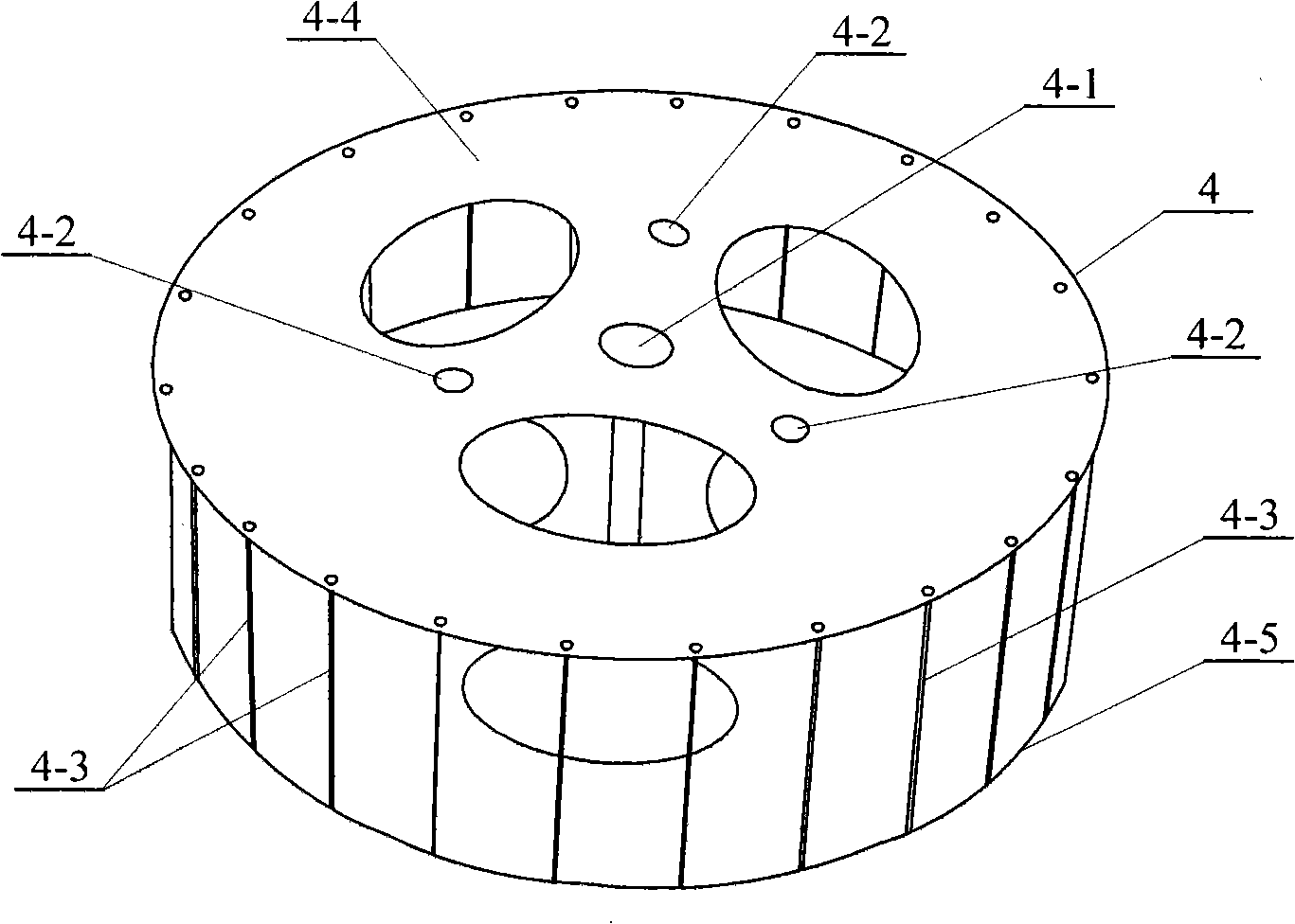
[0009] Specific implementation three: (see Figure 4 ) The center drum 4 described in this embodiment is composed of a central positioning column 4-1, three auxiliary positioning columns 4-2, a plurality of side columns 4-3, an upper plate 4-4 and a lower plate 4-5. 4-4 and the lower plate 4-5 are arranged corresponding to each other up and down, the central positioning column 4-1 is arranged on the axis of the upper plate 4-4 and the lower plate 4-5, and the two ends of the central positioning column 4-1 are respectively connected with the upper plate. 4-4 is fixedly connected with the lower plate 4-5, three auxiliary positioning columns 4-2 are arranged on the outer side of the central positioning column 4-1, and two ends of the three auxiliary positioning columns 4-2 are respectively connected with the upper plate 4-4 and the upper plate 4-2. The lower plate 4-5 is fixedly connected, a plurality of side columns 4-3 are arranged at the edge between the upper plate 4-4 and th...


PUM


Abstract

The invention provides a rigidizable inflatable deployment radial rib brace type offset parabolic reflector antenna, relating to a parabolic antennal. The aim of the invention is for solving problems that the antennal used for satellites of existing mechanical structure has low unfolding or folding efficiency, great weight and high cost, and low unfolding reliability in the folding course caused by complex driving mechanism. One side of a plurality of radial ribbed slabs of the invention are all connected with a central drum and the other side of a plurality of radial ribbed slabs are all connected with an inflatable support ring by a hanging guy. An elastic reflecting surface net is arranged on the lower side of a plurality of radial ribbed slabs and one side of three inflatable support tubes are all connected with the inflatable support ring. The whole antenna is in curling and folding state initially, and the inflatable support tubes are firstly aerated after entering after injection. The invention combines the radial ribs autologous rebound force to unfold the whole reflector structure under unfolding pulling of the inflatable support tubes and the inflatable support ring, and the invention can maintain the structure shape of the antenna without continuous aerating after the inflatable support tubes and the inflatable support ring are completely rigidized and hardened.

Description

technical field [0001] The present invention relates to a parabolic antenna. Background technique [0002] At present, most of the satellite antennas have mechanical structures. The satellite antennas with this mechanical structure have low unfolding and folding efficiency, heavy antenna weight and high cost. During the unfolding process, due to the complicated driving mechanism, the unfolding reliability is low. Satellite antennas with existing mechanical structures can no longer meet the requirements of large-scale and light-weight antenna structures. SUMMARY OF THE INVENTION [0003] The purpose of the present invention is to solve the problem that the existing satellite antenna has many mechanical structures. The satellite antenna with this mechanical structure has low unfolding and folding efficiency, heavy antenna weight and high cost, and its driving mechanism is complicated in the unfolding process. To solve the problem of low deployment reliability, a rigid infla...

Claims


Application Information

Patent Timeline
IPC IPC(8): H01Q19/12H01Q15/16
Inventor 王长国杜星文谭惠丰谢志民苗常青王友善
Owner HARBIN INST OF TECH
Why Eureka
Try Eureka