Rigidizable inflating-expansion radial direction rib support type offset-feed paraboloidal antenna
A parabolic antenna, inflatable deployment technology, applied to antennas, electrical components and other directions, can solve the problems of low deployment reliability, complex driving mechanism, heavy antenna weight, etc., to achieve high deployment reliability, reduced folding volume, and light weight.
- Summary
- Abstract
- Description
- Claims
- Application Information
AI Technical Summary
Problems solved by technology
Method used
Image
Examples
specific Embodiment approach 1
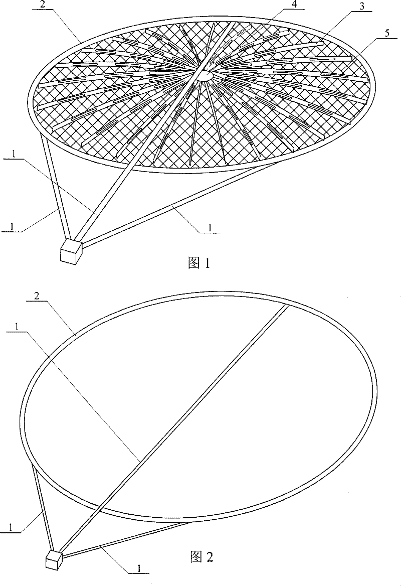
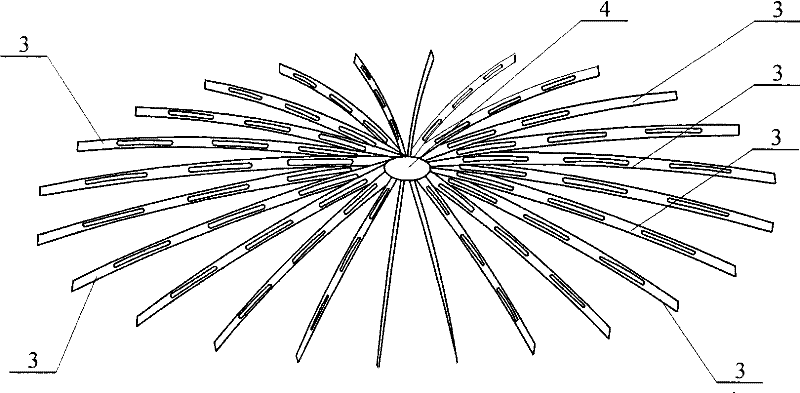
[0007] Specific implementation mode one: (see Figure 1 to Figure 5 ) This embodiment consists of three inflatable support tubes 1, an inflatable support ring 2, multiple radial ribs 3, a central drum 4, elastic reflective surface nets 5 and suspension wires 6, and multiple radial ribs 3 are radially arranged , one end of a plurality of radial ribs 3 is connected with the center drum 4, the other end of the plurality of radial ribs 3 is connected with the inflatable support ring 2 by a suspension wire 6, and the elastic reflection surface net 5 is arranged on a plurality of On the lower side of the radial rib 3, one end of the three inflatable support tubes 1 is connected to the inflatable support ring 2, and the other ends of the three inflatable support tubes 1 are gathered together, and the inflatable support tube 1 and the inflatable support ring 2 are formed by Made of rigidizable composite film material.
specific Embodiment approach 2
[0008] Specific implementation mode two: (see Figure 5 ) The radial ribs 3 in this embodiment are provided with strip-shaped through holes 7 . The purpose of the hollow design of the radial ribs 3 is to reduce the weight of the antenna. Others are the same as in the first embodiment.
specific Embodiment approach 3
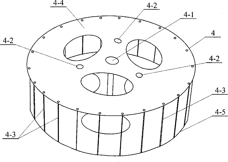
[0009] Specific implementation mode three: (see Figure 4 ) The center drum 4 described in this embodiment is composed of a central positioning column 4-1, three auxiliary positioning columns 4-2, a plurality of side columns 4-3, an upper plate 4-4 and a lower plate 4-5, and the upper plate 4-4 and the lower plate 4-5 are arranged corresponding to each other up and down, the central positioning column 4-1 is arranged on the axis of the upper plate 4-4 and the lower plate 4-5, and the two ends of the central positioning column 4-1 are connected with the upper plate respectively. 4-4 is fixedly connected with the lower plate 4-5, and the three auxiliary positioning columns 4-2 are arranged on the outside of the center positioning column 4-1, and the two ends of the three auxiliary positioning columns 4-2 are connected with the upper plate 4-4 and the upper plate 4-4 respectively. The lower plate 4-5 is fixedly connected, and a plurality of side columns 4-3 are arranged at the ed...
PUM
 Abstract
Description
Claims
Application Information
 - R&D
- Intellectual Property
- Life Sciences
- Materials
- Tech Scout
- Unparalleled Data Quality
- Higher Quality Content
- 60% Fewer Hallucinations
Browse by: Latest US Patents, China's latest patents, Technical Efficacy Thesaurus, Application Domain, Technology Topic, Popular Technical Reports.
© 2025 PatSnap. All rights reserved.Legal|Privacy policy|Modern Slavery Act Transparency Statement|Sitemap|About US| Contact US: help@patsnap.com


