
Device for supporting cable

A technology for supporting devices and cables, which is applied in the installation of cables, the arrangement of cables between relative moving parts, and circuits, etc., which can solve the problems of large installation space, inability to swing horizontally, and failure of connecting components to have the same shape, so as to achieve improvement assembling effect

Active Publication Date: 2008-10-15
SUMITOMO WIRING SYST LTD
View PDF1 Cites 15 Cited by
  • Summary
  • Abstract
  • Description
  • Claims
  • Application Information

AI Technical Summary

Problems solved by technology

In other words, the cable passing the link member 1a at the leading end swings in the vertical direction, but cannot swing in the lateral direction, and the lateral swing movement is caused by the link member 1 connected to the link member 1a and the following link member 1
As a result, the cables are unable to perform lateral swinging movement at positions close to the cable support member 3, twisting in the coupling member
[0012] Moreover, since the connection direction of the vertically swingable coupling member 1a at the leading end to the support member 3 via the pin and the connection direction of the laterally swingable coupling member 1a via the pin are different in Patent Document 1, all the coupling members cannot have Same shape, and the coupling member 1a at the leading end needs to be set separately
This increases the number of parts, and since the coupling member 1a at the leading end is necessary, there is a problem that a larger installation space is required

Method used


Image

  • Device for supporting cable
  • Device for supporting cable
  • Device for supporting cable

Examples


Embodiment Construction

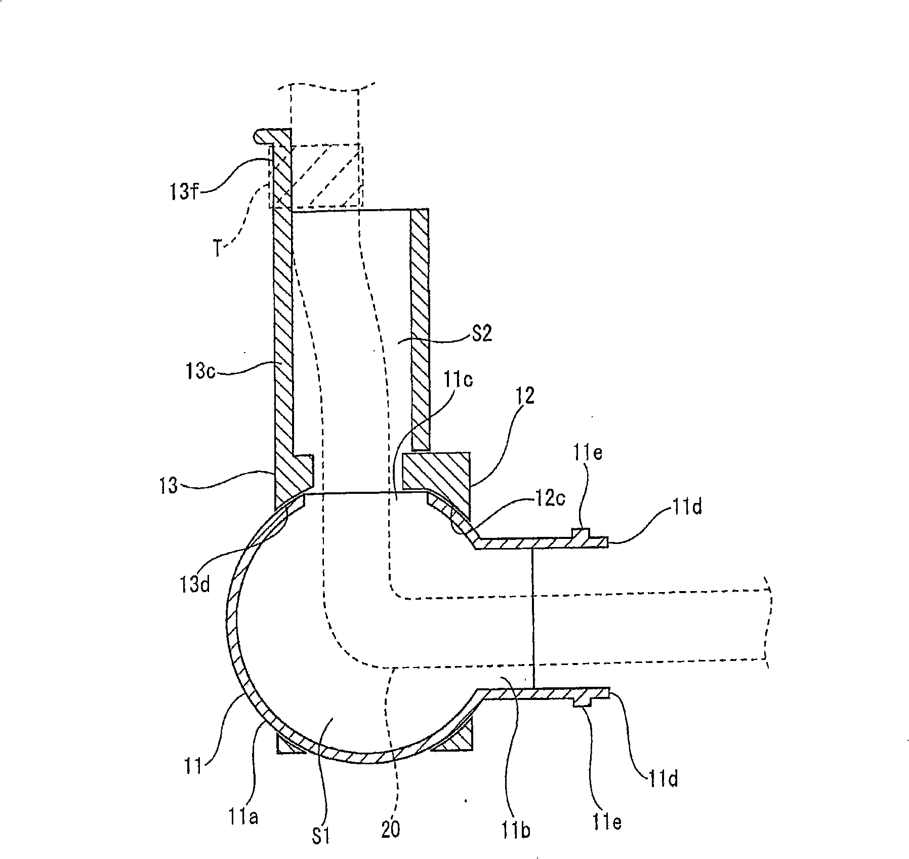
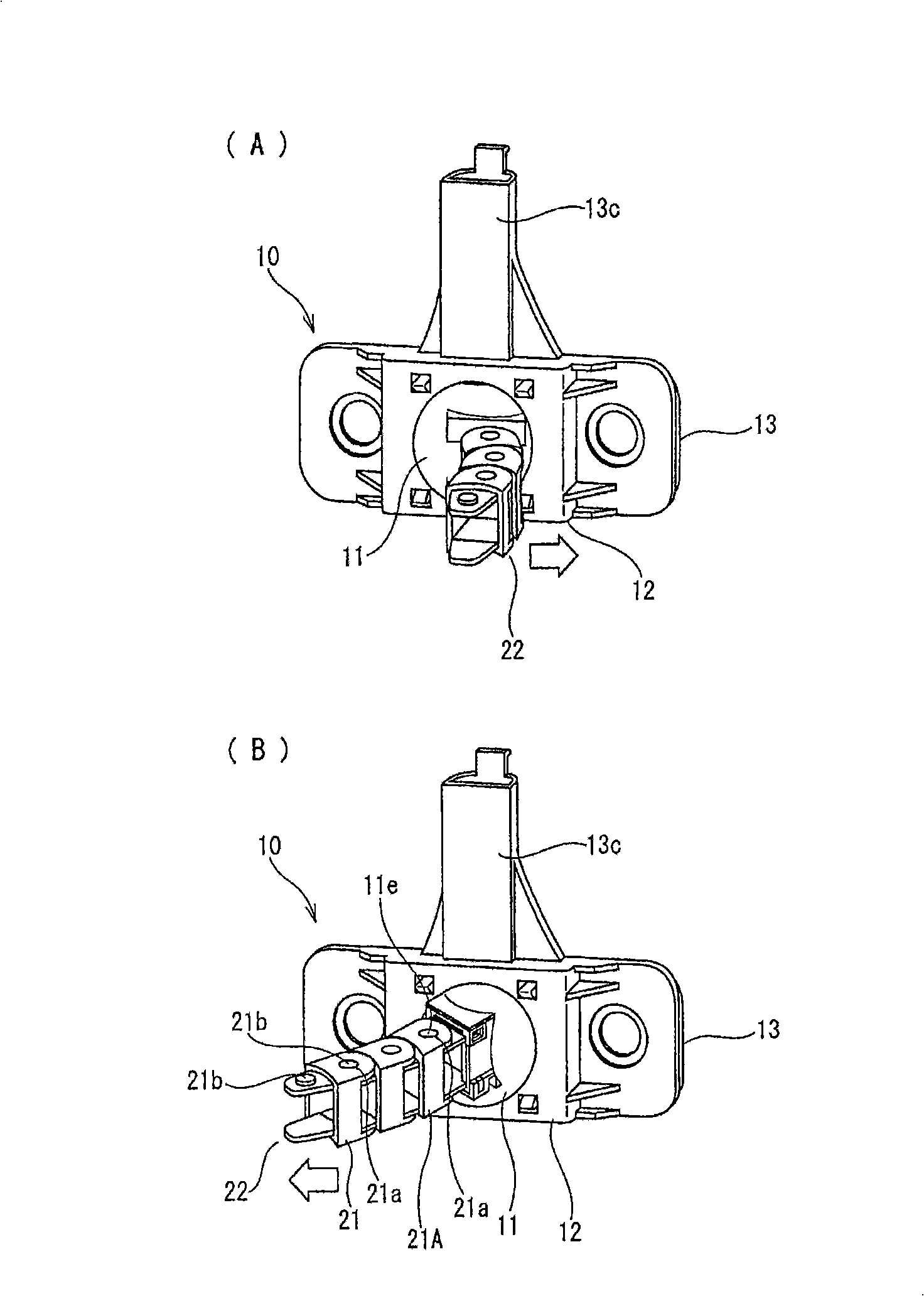
[0077] attached Figures 1 to 5 A first embodiment of the present invention is shown, and a cable support device 10 (hereinafter, referred to as "support device 10") is used to support a cable 20, which is arranged to straddle a motor vehicle, by allowing the cable to be inserted therethrough. body (not shown) and a sliding door (not shown) slidably connected to the vehicle body.

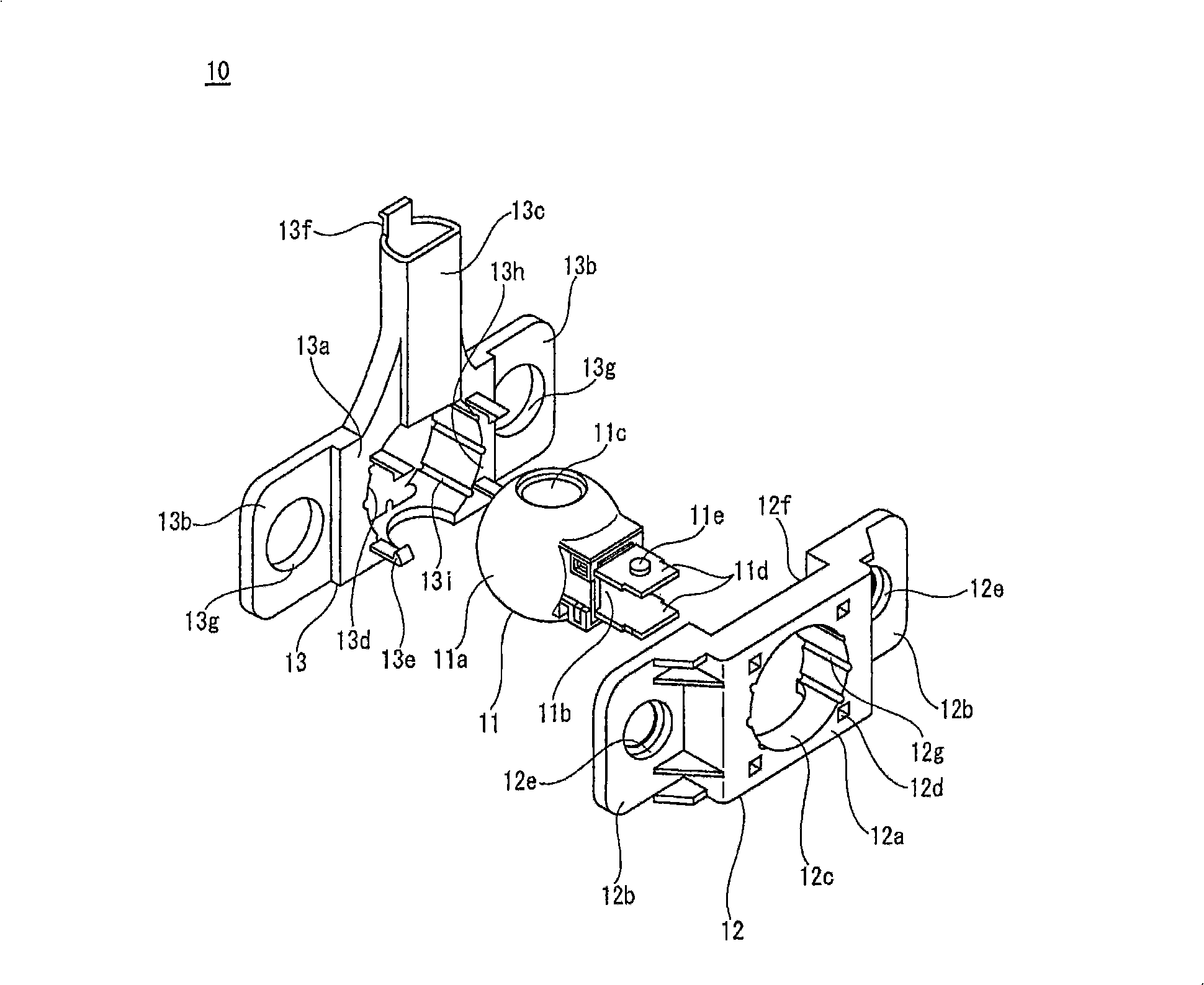
[0078] as attached figure 1 As shown in , the support device 10 includes a spherical guide member 11 made of resin, and a pair of first and second support members 12, 13 that rotatably hold the spherical guide member 11 therebetween.

[0079] The spherical member 11 has a spherical frame body 11a, a first opening 11b communicating with the spherical hollow portion S1 of the frame body 11a is formed in one side surface of the frame body 11a, and a second opening 11c communicating with the hollow portion S1 is formed. In the upper side at a distance of 90° from the first opening 11b. The first ope...


PUM


Abstract

A device for supporting a cable installed between a vehicle body and a movable member movably connected to the vehicle body. The device has a guide member and support members. The guide member has a first opening for cable insertion, communicating with a hollow section of a frame body, and a second opening for cable insertion, communicating with the hollow section with a predetermined angle less than 180 degrees relative to the first opening. On the outer surface of the frame body is provided a three-dimensional circular arch surface. The support members rotatably hold the three-dimensional circular arch surface of the guide member and are fixed to the vehicle body and / or movable member. The cable is made to penetrate from the first opening of the guide member through the hollow section to the second opening, and the guide member can follow a change in the angle of the cable in top-bottom, left-right, and oblique directions.

Description

technical field [0001] The present invention relates to cable support devices and is particularly designed to support cables spanning between a sliding door of a vehicle and the vehicle body in such a manner that it can be moved vertically, laterally and vertically as the sliding door is opened and closed. The tilt direction follows the cable as it changes its angle. Background technique [0002] Electronic components such as power windows and door locks are installed in doors of motor vehicles, and cables (door harnesses) for constant supply of electric power are connected to these electronic components. The cable is arranged to extend toward the vehicle body and to be connected to the power supply side cable in the vehicle body. [0003] If the door is a sliding door, it can move both vertically and laterally perpendicular to the sliding direction when closing and opening. Thus, the angle of the cables spanning between the sliding door and the vehicle body changes with r...

Claims


Application Information

Patent Timeline
Patent Type & Authority Applications(China)
IPC IPC(8): H02G11/00B60R16/02
CPCH02G11/006Y10T403/32631B60R16/0215H02G11/00
Inventor 村山繁树小林良尚
Owner SUMITOMO WIRING SYST LTD
Learn More