Method for determining correction factor of belt balance real object simulating detection device

A detection device and correction coefficient technology, which is applied in measuring devices, weighing equipment for continuous material flow, and weighing equipment testing/calibration, etc., can solve the problem of high device cost, affecting the development of circular chain code technology, and the development prospect of circular chain code Restrictions and other issues, to overcome the effect of gravity error

Active Publication Date: 2008-10-29
BEIJING CHUNHAI TECH DEV
View PDF0 Cites 16 Cited by
  • Summary
  • Abstract
  • Description
  • Claims
  • Application Information

AI Technical Summary

Problems solved by technology

[0003] However, in order to correct the physical material test of the belt scale analog physical detection device - the circular chain code, the site where the belt scale and the circular chain code are installed must be equipped with a physical material detection device, and the device is expensive and labor-intensive to detect.
Therefore, determining the correction coefficient of cyclic chain codes has become a bottleneck affecting the development of cyclic chain code technology, which limits the development prospects of cyclic chain codes full of vitality.

Method used


Image

  • Method for determining correction factor of belt balance real object simulating detection device
  • Method for determining correction factor of belt balance real object simulating detection device
  • Method for determining correction factor of belt balance real object simulating detection device

Examples


Embodiment Construction

[0035] The principles and methods of the present invention will be further described below in conjunction with the accompanying drawings and specific embodiments, so as to help understand the content of the present invention.

[0036] 1. Some basic concepts about belt tension

[0037] 1.1 Belt tension conditions and hammer mass under normal operation of the belt conveyor

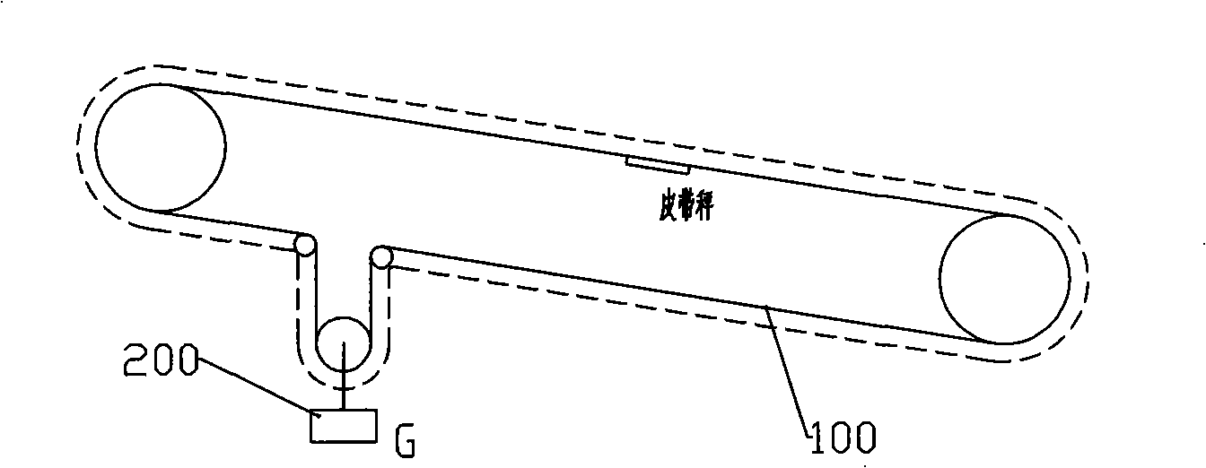
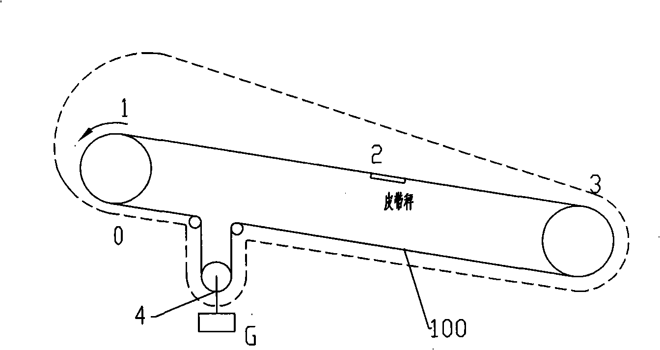
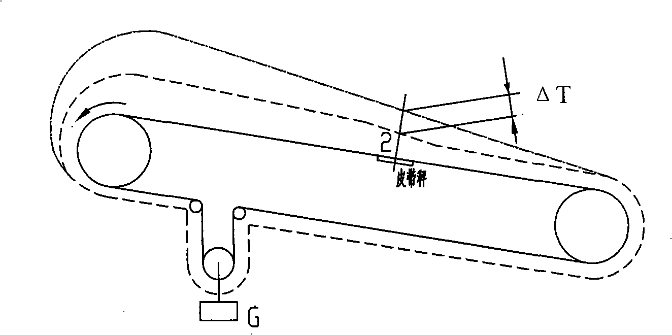
[0038] The tension of the belt varies over the entire length, and there are many influencing factors. In order to ensure the normal operation of the belt conveyor, the tension of the belt must meet two conditions:

[0039] 1.1.1 The belt conveyor must be able to work normally under the premise of a certain belt tension. Only when the belt tension reaches a certain level can sufficient friction be generated between the driving pulley and the belt (the circumferential force on all pulleys is transmitted to the belt through friction. on the belt) to keep the belt from slipping. To ensure that the belt conveyo...


PUM


Abstract

The invention discloses a method of belt tension compensation to replace a method of adopting a real object material detecting device to determine that a belt scale simulates a correction factor of an object detecting device. The method comprises the steps of respectively determining the running resistance generated by cycling chain weights and materials to a belt conveyor, thereby determining the difference value between the belt tension and the weight of a tension weight; using a weight with mass of G to vertically tighten the position of a belt conveyor weight tension device of the belt scale detected by the cycling chain weights, so as to measure the length of the belt and the height of the weight; adding a front and a back displacement amounts according to the mass of the weight; calculating the average value of accumulative amount: W chain weight G and W chain weight (G plus DeltaG) by using the cycling chain weights to detect the belt scale for a plurality of times; calculating a velocity correction factor and C velocity, according to the formula that C velocity is equal to 1 / (1 minus 2 (h1 minus h2) / L); and calculating the cycling chain weight correction factor, according to the formula that C is equal to 1 plus (C velocity*W chain weight (G plus DeltaG) minus W chain weight G) / (C velocity* W chain weight(G plus DeltaG)).

Description

technical field [0001] The invention relates to a calibration method for the accuracy of industrial measuring instruments. Specifically, it is a new method for determining the correction coefficient of an electronic belt scale analog object detection device for testing the electronic belt scale. Background technique [0002] At present, the belt scale analog object detection device widely used in the industrial field to detect electronic belt scales has the most characteristic main part, that is, the standard component transmitted through the upper level value is a circular chain code, which can usually be directly called The belt scale analog object detection device is a circular chain code. Because of its scientific principle, ingenious design, reasonable structure, low cost, convenient operation and good repeatability, it has initially shown its vitality in the detection of electronic belt scales. After being corrected by the physical material test, the detection accurac...

Claims


Application Information

Patent Timeline
IPC IPC(8): G01G23/01G01G11/00
Inventor 李春孝周有守许振国
Owner BEIJING CHUNHAI TECH DEV
Why Eureka
Try Eureka