Cleaning tool

A technology for cleaning tools and floors, applied to cleaning equipment, cleaning machinery, carpet cleaning, etc., can solve problems such as difficult to remove, difficult to collect and capture larger objects

Inactive Publication Date: 2008-10-29
3M INNOVATIVE PROPERTIES CO
View PDF2 Cites 3 Cited by
  • Summary
  • Abstract
  • Description
  • Claims
  • Application Information

AI Technical Summary

Problems solved by technology

Usually the tool has a rectangular shape and when dirt gets into the corners it is very difficult to remove it
Additionally, larger objects are difficult to collect and capture with rectangular tool users

Method used


Image

  • Cleaning tool
  • Cleaning tool
  • Cleaning tool

Examples


Embodiment Construction

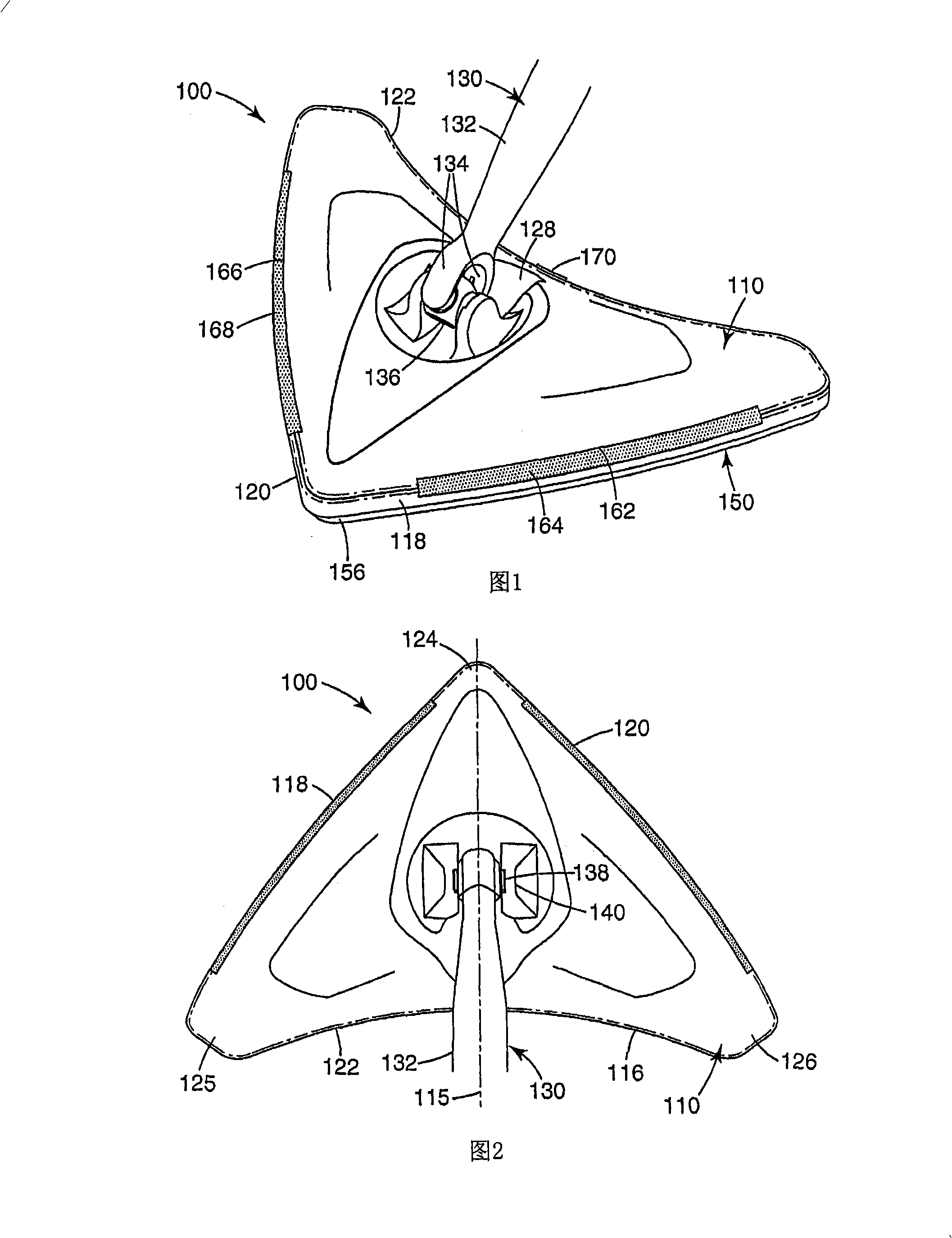
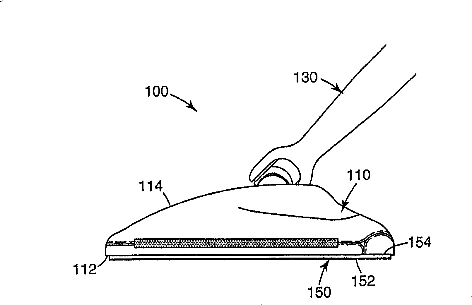
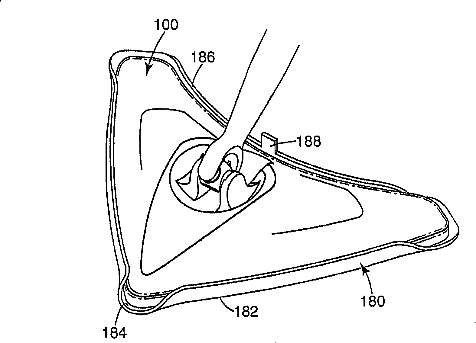
[0018] FIG. 1 is a perspective view of one embodiment of a cleaning implement 100 according to the present invention. FIG. 2 is a top view of the cleaning tool 100 in FIG. 1, image 3 is a side view of the cleaning tool 100 in FIG. 1 . Floor cleaning tool 100 includes backing 110, handle 130, conformable support 150, and wiper 180 (such as Figure 4 shown, connected to the part of the cleaning tool 100).

[0019] Backing 110 is made of a rigid material, such as metal or plastic. The backing 110 includes a first surface 112 and a second surface 114 . Generally, the backing 110 includes a generally triangular-shaped perimeter 116 having an entrainment point 124, a left drag corner, and a right drag corner. Backing 110 is generally symmetrical along longitudinal axis 115 . The triangular perimeter 116 includes a first edge 118 , a second edge 120 , and a third edge 122 .

[0020] The first edge 118 and the second edge 120 meet to form an entrainment point 124 . Preferably, ...


PUM


Abstract

The present invention relates to a floor cleaning tool. In one embodiment the floor cleaning tool comprises a backing and a handle. The backing comprises a first surface and a second surface. The handle is attached to the second surface of the backing apparatus. The backing has a generally triangular perimeter having a first edge, a second edge, and a third edge. A portion of the first edge is curved and a portion of the second edge is curved. The first edge and second edge meet at a leading point. The third edge is concave. The floor cleaning tool is capable of supporting a wipe.

Description

technical field [0001] The present invention relates to cleaning implements. More particularly, the present invention relates to floor cleaning implements capable of supporting wipes. Background technique [0002] Consumers use various types of floor cleaning implements to clean floors. Brooms and mops are examples of such tools. Brooms are effective at cleaning corners because the bristles reach deep into the corners and pull out the dirt. However, a broom by itself cannot pick up dirt and debris and cannot remove dirt and debris stuck to the floor. [0003] Fabric mop heads are another type of floor cleaning tool with string or yarn sticking out of the mop head. The floor cleaning implement may also have a sponge mop head. Both types of cleaning tools are capable of retaining water. Typically, the user must use a separate chemical cleaning product and water to clean the floor. Using separate cleaning products can be cumbersome and require consumers to store crude ch...

Claims


Application Information

Patent Timeline
IPC IPC(8): A47L13/254A47L13/256A47L13/20
CPCA47L13/24A47L13/10A47L13/20A47L13/254A47L13/256
Inventor 佩里·S·多特曼斯科特·J·图曼戴安娜·R·沃尔克约翰·M·西蒙马克·D·瑟利马克·W·纳尔森迈克尔·J·库贝斯拜伦·E·特罗特亚瑟·V·兰约翰内斯·N·加斯顿道格拉斯·J·瓦诺努姆史蒂文·A·博德里
Owner 3M INNOVATIVE PROPERTIES CO
Why Eureka
Try Eureka