Transmission shift device with variable gate blocking force

A technology of transmission and sub-transmission, which is applied in the direction of mechanical equipment, components with teeth, transmission control, etc., and can solve problems such as complex structures

Active Publication Date: 2008-10-29
ZF FRIEDRICHSHAFEN AG
View PDF3 Cites 7 Cited by
  • Summary
  • Abstract
  • Description
  • Claims
  • Application Information

AI Technical Summary

Problems solved by technology

[0009] Although the known electro-pneumatic shifting unit has some advantages, its structure is rather complex
In addition, this shifting unit has the technical problem that the locking force for holding the shifting and selection shaft in the channel for the third and fourth gears must be considerable, so that due to the increased actuation imposed by this The force reliably signals the driver when the selector lever is actuated, so that the split-group shifting begins, when incorrect gear changes are to be avoided

Method used


Image

  • Transmission shift device with variable gate blocking force
  • Transmission shift device with variable gate blocking force
  • Transmission shift device with variable gate blocking force

Examples


Embodiment Construction

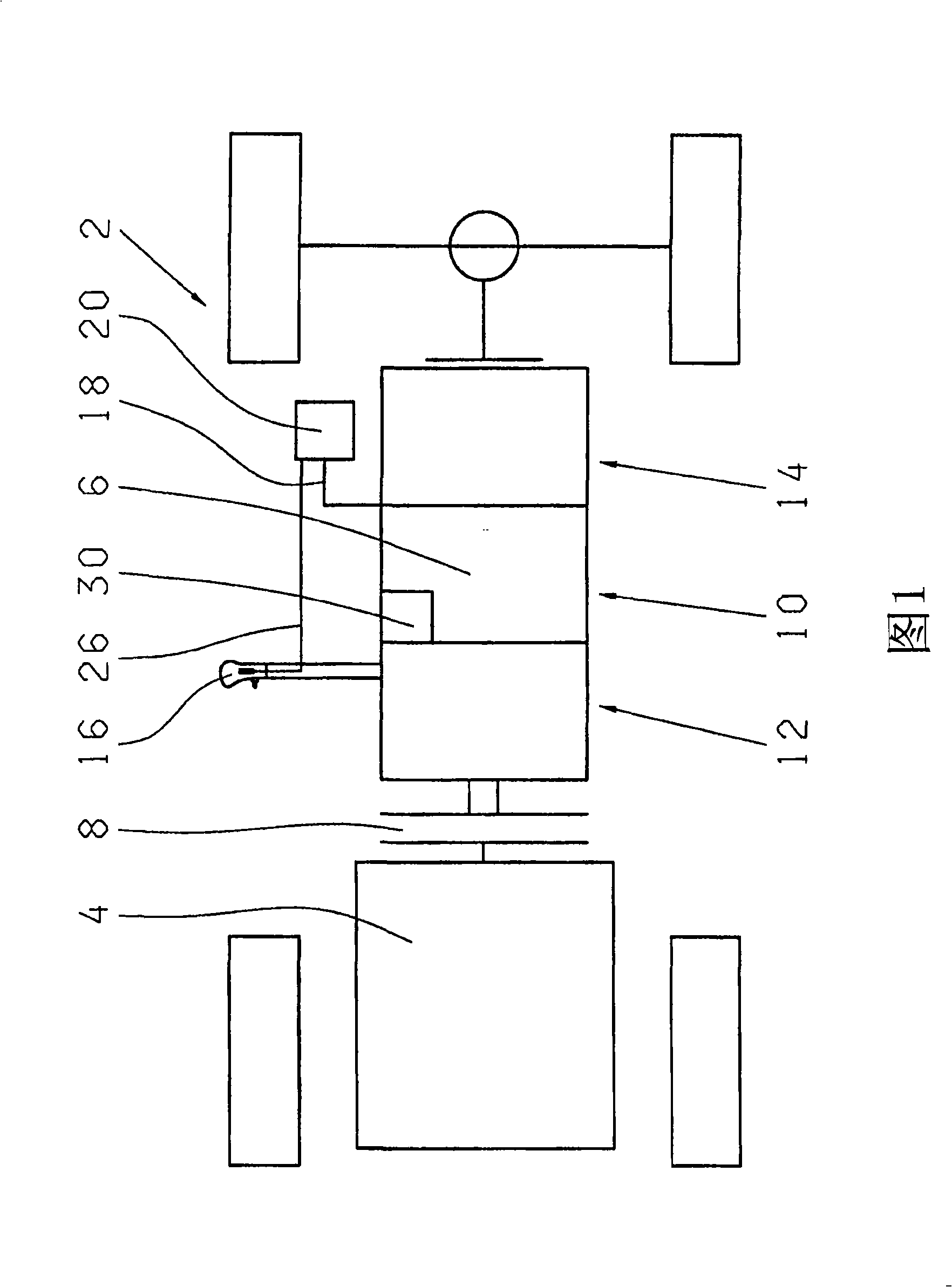
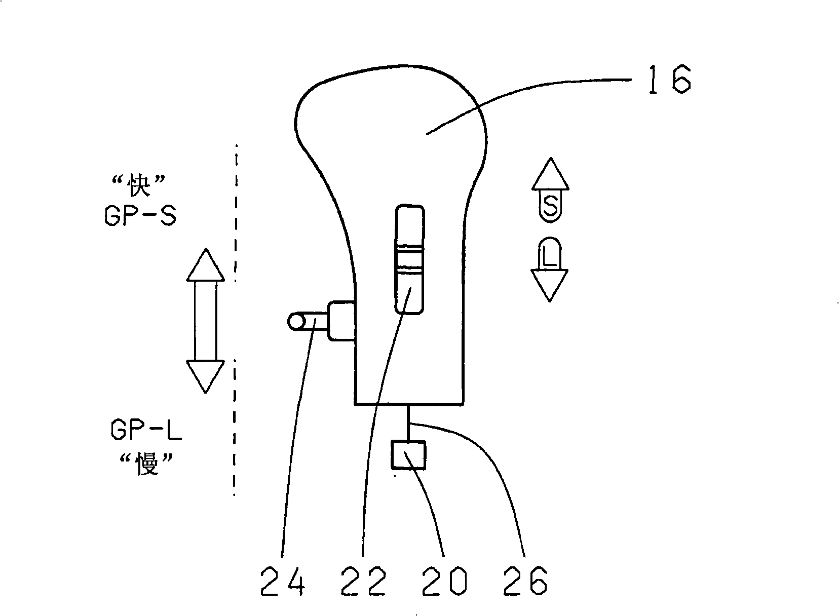
[0032]FIG. 1 thus shows a motor vehicle 2 comprising an engine 4 , a transmission 6 and a clutch 8 arranged between them. The transmission 6 has a main transmission 10 , a splitter 12 and a splitter 14 . The main transmission 10 is manually shifted by the driver of the vehicle via a selector lever 16 . To this end, the selector lever 16 is operatively connected via a shift and select shaft 32 and a transmission shifting device 30 to a transmission-side shifting element, not shown here. The transmission shifting device 30 also includes a blocking element, which prevents unintentional shifting operations and / or notifies the driver of this at least during a shifting operation on the selector lever side. The selector lever 16 can also be connected to a transmission shifting device 30 via a pneumatic line (not shown). The transmission 6 is generally connected via an electrical connection line 18 to the electronic control unit 20 and the selector lever is connected to the electron...


PUM


Abstract

The present invention relates to a transmission shift device (30) for a transmission (6) having a range group transmission (14) and a selector lever (16) with a superposed H-shaped shift pattern, in which transmission shift device (30) a shift- and selector shaft (32) is operatively connected at one end (34) to the selector lever (16) and at the other end to transmission-side shift means, having a blocking device which can be actuated by means of a pressure medium and which prevents, or at least notifies a driver of a motor vehicle of, an inadvertent selection of transmission gears in the event of a range group shift, in such a way that the shift- and selector shaft (32) can, in the event of a range group shift, be displaced autonomously from one shift gate (G5-G6) to the shift gate (G3-G4) of the two next lowest gears (G3, G4).; Said transmission shift device is also designed, so as to avoid undesired incorrect shifts in the event of a range group shift and to permit downshifts across several gear stages, in such a way that the shift- and selector shaft (32) can be displaced from one shift gate (G5-G6) to the shift gate (G3-G4) of the next lowest gears with a force (F1 to F2) which varies over the displacement travel.

Description

technical field [0001] The invention relates to a transmission shifting device according to the preamble of claim 1 . Background technique [0002] The transmissions of large cargo (operating) vehicles can usually be divided into main transmissions, split-type auxiliary transmissions and sub-regional auxiliary transmissions. This type of transmission has a shifting device supported by a pneumatic device, which can be shifted pneumatically in the splitter and splitter, and manually by the driver in the main transmission. In some cases the applied force can be supported by pneumatics. [0003] Electronic control units are now increasingly being used to control conventional vehicle transmissions. This arrangement also serves, inter alia, to prevent shifting in the transmission, ie, due to other conditions, a particularly high vehicle speed is not permitted in the target gear to be shifted. [0004] Such a pneumatic shifting device with mechanical protection against incorrect...

Claims


Application Information

Patent Timeline
Patent Type & Authority Applications(China)
IPC IPC(8): F16H61/16F16H63/34F16H61/18F16H61/70
CPCF16H2059/0286F16H61/70F16H61/24F16H59/02F16H61/16F16H2061/166F16H61/18Y10T74/20085Y10T74/20018
Inventor 迪特尔·菲舍尔克劳斯·施佩特
Owner ZF FRIEDRICHSHAFEN AG
Why Eureka
Try Eureka