
Control device for automatic transmission for vehicle

A technology for automatic transmissions, controls, applied in the direction of transmission controls, elements with teeth, belts/chains/gears, etc.

Active Publication Date: 2013-08-14
TOYOTA JIDOSHA KK
View PDF12 Cites 3 Cited by
  • Summary
  • Abstract
  • Description
  • Claims
  • Application Information

AI Technical Summary

Problems solved by technology

Among them, the above-mentioned problems are unknown problems, and there has not been proposed a proposal that can properly perform the fail-safe function when an abnormality occurs in the electronic control device itself without newly providing a fail-safe valve or hardware for performing a fail-safe operation.

Method used


Image

  • Control device for automatic transmission for vehicle
  • Control device for automatic transmission for vehicle
  • Control device for automatic transmission for vehicle

Examples


Embodiment

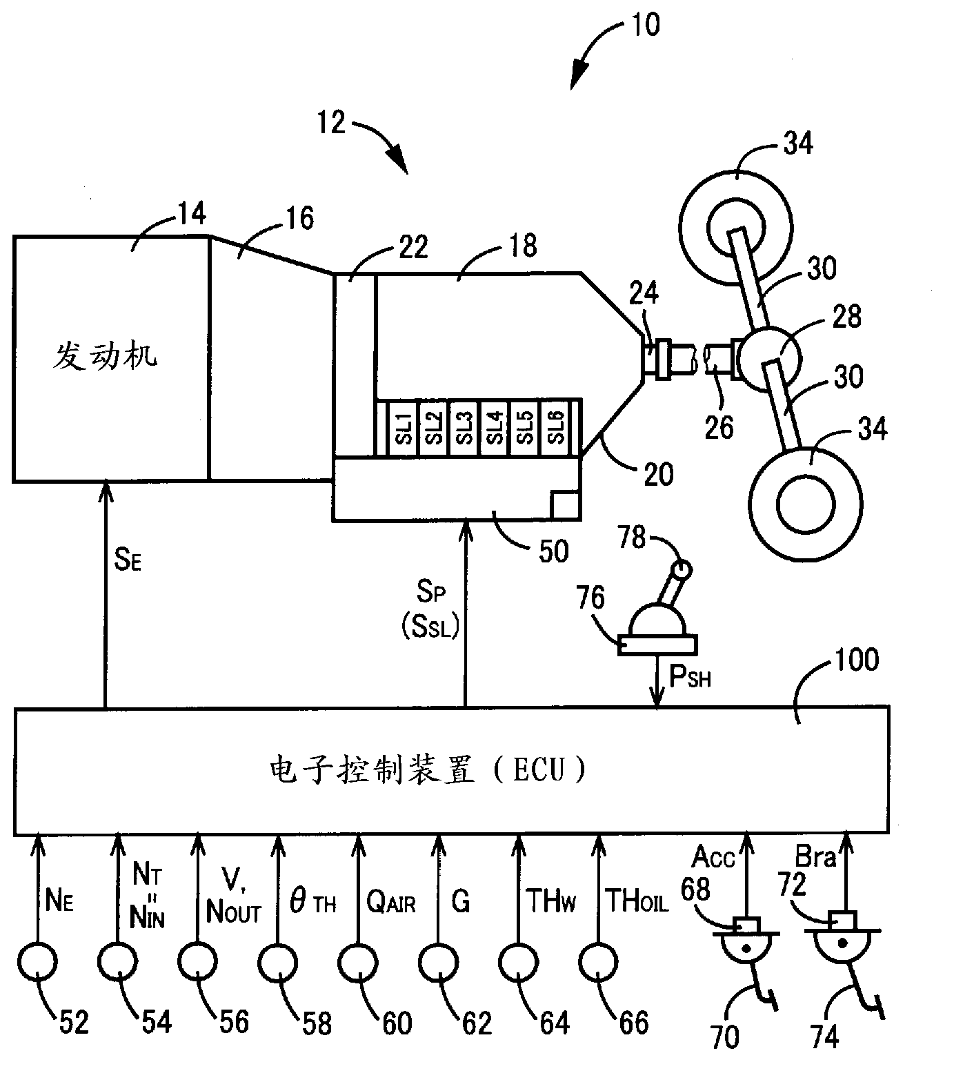
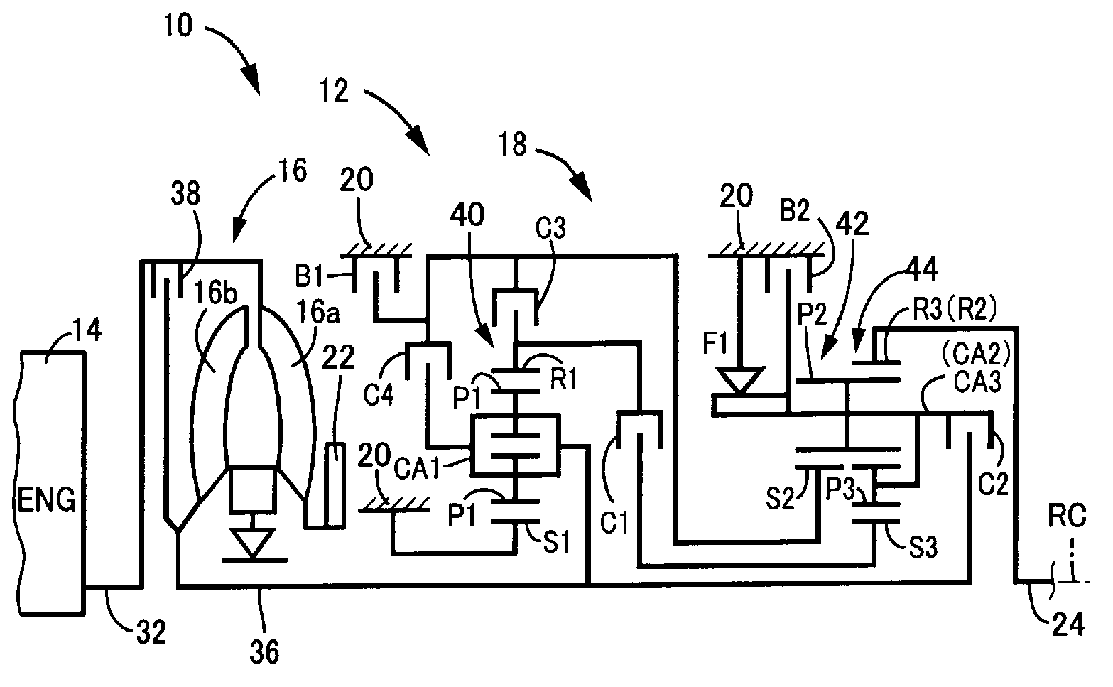
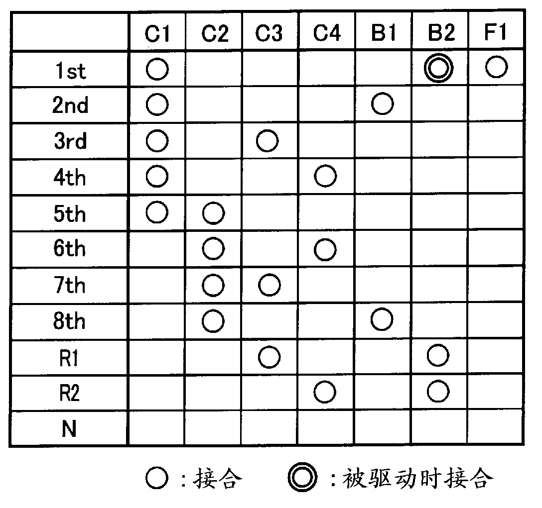
[0030] figure 1 It is a diagram for explaining the schematic structure of the power transmission path from the engine 14 to the drive wheels 34 of the vehicle 10 to which the present invention is applied, and it is an automatic transmission 18 for the vehicle (hereinafter referred to as the automatic transmission 18 ) for the output control of the engine 14. ) is provided in the main part of the control system of the vehicle 10 for explanation. in addition, figure 2 It is a main diagram explaining the automatic transmission 18 . Among them, the torque converter 16, the automatic transmission 18, etc. are configured approximately symmetrically with respect to the center line (shaft center RC). figure 2 , the lower half of the centerline is omitted. in addition, figure 2 The shaft center RC in is the rotation shaft center of the engine 14 and the torque converter 16 .

[0031] exist figure 1 , figure 2 Among them, the power transmission device 12 for a vehicle (herein...


PUM


Abstract

A control apparatus for a vehicular automatic transmission configured to selectively establish a plurality of shift positions by respective combinations of frictional coupling devices of a plurality of frictional coupling devices in an engaged state thereof, with output hydraulic pressures of respective ones of a plurality of solenoid valves provided in a hydraulic control circuit, includes a fail-safe control portion configured to perform a predetermined fail-safe function when shifting direction values requiring a shifting control of said vehicular automatic transmission and shifting output values respectively generated according to said shifting direction values are not coincident with each other, said shifting output values being represented by respective electric signals for driving said plurality of solenoid valves.

Description

technical field [0001] The present invention relates to a control device for an automatic transmission for a vehicle that performs shifting using a plurality of electromagnetic valves provided in a hydraulic control circuit. Background technique [0002] There is known an automatic transmission for a vehicle that selectively engages any one of a plurality of frictional engagement devices using the output hydraulic pressure from a plurality of electromagnetic valves provided in a hydraulic control circuit to establish one of a plurality of shift stages. control device. In the above-mentioned hydraulic control circuit, for example, an abnormal output of the solenoid valve may be caused by an abnormality of the electronic control device itself which judges the shifting of the automatic transmission and commands the output of the electric signal. When such an abnormal output of the solenoid valve occurs, in addition to the friction engagement device involved in the formation of...

Claims


Application Information

Patent Timeline
Patent Type & Authority Applications(China)
IPC IPC(8): F16H61/12
CPCF16H2061/1232F16H61/686F16H61/68F16H2061/1268F16H61/12F16H2061/1208Y10T74/19251
Inventor 斋藤秀典杉村敏夫
Owner TOYOTA JIDOSHA KK
Learn More