Imaging device, display control method, and program

A display control method and camera technology, applied in image communication, static indicators, cathode ray tube indicators, etc., can solve the problems of not knowing the set value and not being easy for the user to know

Inactive Publication Date: 2008-11-19
SONY CORP
View PDF1 Cites 31 Cited by
  • Summary
  • Abstract
  • Description
  • Claims
  • Application Information

AI Technical Summary

Problems solved by technology

[0005] In existing devices such as digital cameras, various settings can be changed by pressing a button (toggle button) that is provided as hardware on the surface of the device, but it often happens that if the user does not t

Method used


Image

  • Imaging device, display control method, and program
  • Imaging device, display control method, and program
  • Imaging device, display control method, and program

Examples


Embodiment Construction

[0030] Hereinafter, embodiments of the present invention will be described with reference to the drawings.

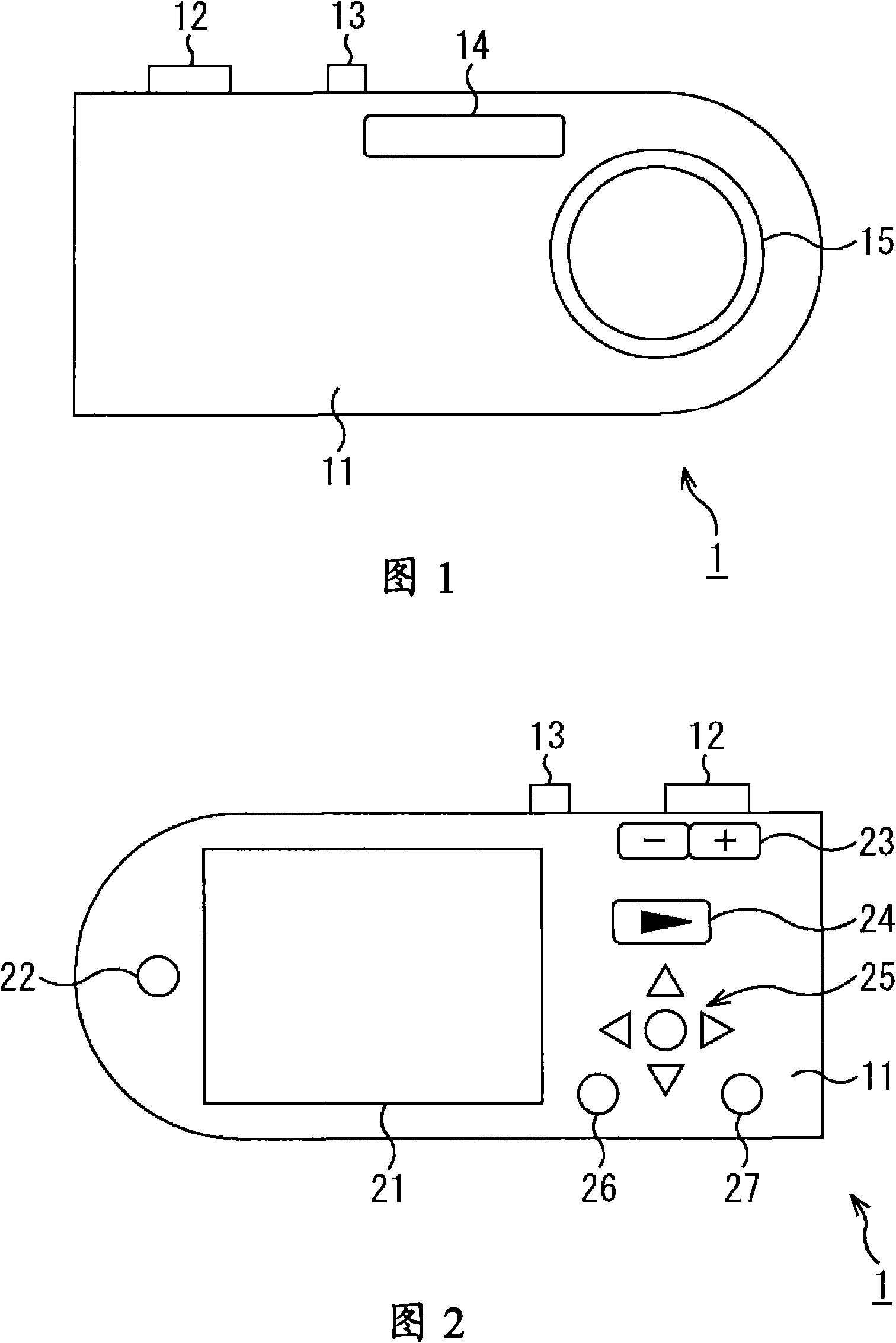
[0031] 1 and 2 are schematic diagrams showing an example of the external configuration of a digital camera 1 as an imaging device according to an embodiment of the present invention.

[0032] In FIGS. 1 and 2 , corresponding parts are denoted by the same symbols. In addition, the case of applying the present invention to a digital camera will be described below, but it can be applied to various devices having an imaging function.

[0033] FIG. 1 shows the appearance of the front (the surface viewed from the subject) of the digital camera 1 , and FIG. 2 shows the appearance of the rear (the surface viewed from the photographer).

[0034] As shown in FIG. 1 , on the top of the main body 11 of the digital camera 1, a shutter button (release button) 12 is provided on the left side viewed from the subject side, and a switching power on / off switch is provided almost in the c...


PUM


Abstract

The invention provides an imaging device, display control method, and program for enabling the user to instinctively confirm all the selectable setting values used as setting for imaging and the operation to select a target set value. Each time a toggle button is pressed down, an image (51) indicating a ''macro mode'' (set value) which is one of close-up imaging modes, an image (52) indicating a ''magnifier mode'' (set value), and an image (53) indicating OFF (set value) of a close-up imaging mode are sequentially displayed in order of attention each time the toggle button is pressed down. An outline arrow indicating the order of attention is also shown each time the toggle button is pressed down between two of the images (51 to 53). When the user presses down the toggle button once, the positions of all the images are changed. With this the image given attention is changed. The present invention can be applied to a device having an imaging function.

Description

technical field [0001] The present invention relates to an imaging device, a display control method, and a program, and particularly relates to an imaging device in which a user can intuitively confirm all set values ​​that can be selected as settings related to shooting, and an operation for selecting a target set value , display control method and program. Background technique [0002] In devices such as digital cameras in the prior art, various technical solutions for displaying setting information that are more user-friendly have been proposed. [0003] For example, Patent Document 1 discloses a technique of iconifying device setting information and displaying a plurality of icons on the screen, appropriately enlarging the icons, or displaying setting values ​​indicating setting contents in text. . [0004] Patent Document 1: Japanese Patent Application Laid-Open No. 4-281438 [0005] In existing devices such as digital cameras, various settings can be changed by pres...

Claims


Application Information

Patent Timeline
IPC IPC(8): H04N5/225G03B17/18G09G3/20G09G5/00H04N5/232
CPCH04N5/23293H04N5/23216G03B17/18H04N23/62H04N23/633H04N23/631H04N23/63
Inventor 久纳克敏
Owner SONY CORP
Why Eureka
Try Eureka