
Method for regulating display effect of video signal apparatus according to viewing position and video signal apparatus thereof

A display effect and video technology, applied to color TV components, TV system components, TVs, etc., can solve problems such as inconvenience, adjustment methods and products without adjustment methods and structures, and inability to change the display effect of the display, etc.

Inactive Publication Date: 2009-07-15
ACER INC
View PDF1 Cites 25 Cited by
  • Summary
  • Abstract
  • Description
  • Claims
  • Application Information

AI Technical Summary

Problems solved by technology

[0004] Although the color TV disclosed in the above-mentioned U.S. patent can adjust the image resolution according to the front and rear viewing distances between the remote controller and the TV, when the user changes the viewing position under the same viewing distance, for example, moving from the left to the On the right side, the TV cannot change the display effect of the display according to the user's position (position). The change of the user's horizontal position corresponds to the adjustment of the output settings of the color TV to provide a better display effect
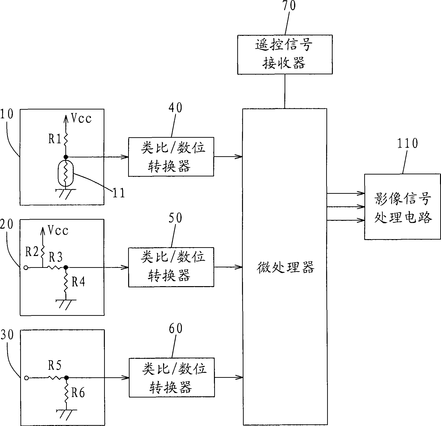
[0005] It can be seen that the above-mentioned existing method for adjusting the display effect of a video device and its video device still have inconveniences and defects in the image adjustment method, product structure and use, and need to be further improved.
In order to solve the above-mentioned problems, the relevant manufacturers have tried their best to find a solution, but no suitable design has been developed for a long time, and there are no suitable adjustment methods and structures for general adjustment methods and products to solve the above-mentioned problems. This is obviously a problem that relevant industry players are eager to solve

Method used


Image

  • Method for regulating display effect of video signal apparatus according to viewing position and video signal apparatus thereof
  • Method for regulating display effect of video signal apparatus according to viewing position and video signal apparatus thereof
  • Method for regulating display effect of video signal apparatus according to viewing position and video signal apparatus thereof

Examples


Embodiment Construction

[0028] In order to further explain the technical means and effects adopted by the present invention to achieve the intended purpose of the invention, the method for adjusting the display effect of a video device according to the viewing position of the user proposed according to the present invention and its video will be described below in conjunction with the drawings and preferred embodiments. The specific implementation, method, structural features and effects of the device are described in detail below.

[0029] The aforementioned and other technical contents, features and effects of the present invention will be clearly presented in the following detailed description of preferred embodiments with reference to the drawings. Through the description of the specific implementation mode, when the technical means and functions adopted by the present invention to achieve the predetermined purpose can be obtained a deeper and more specific understanding, but the accompanying draw...


PUM


Abstract

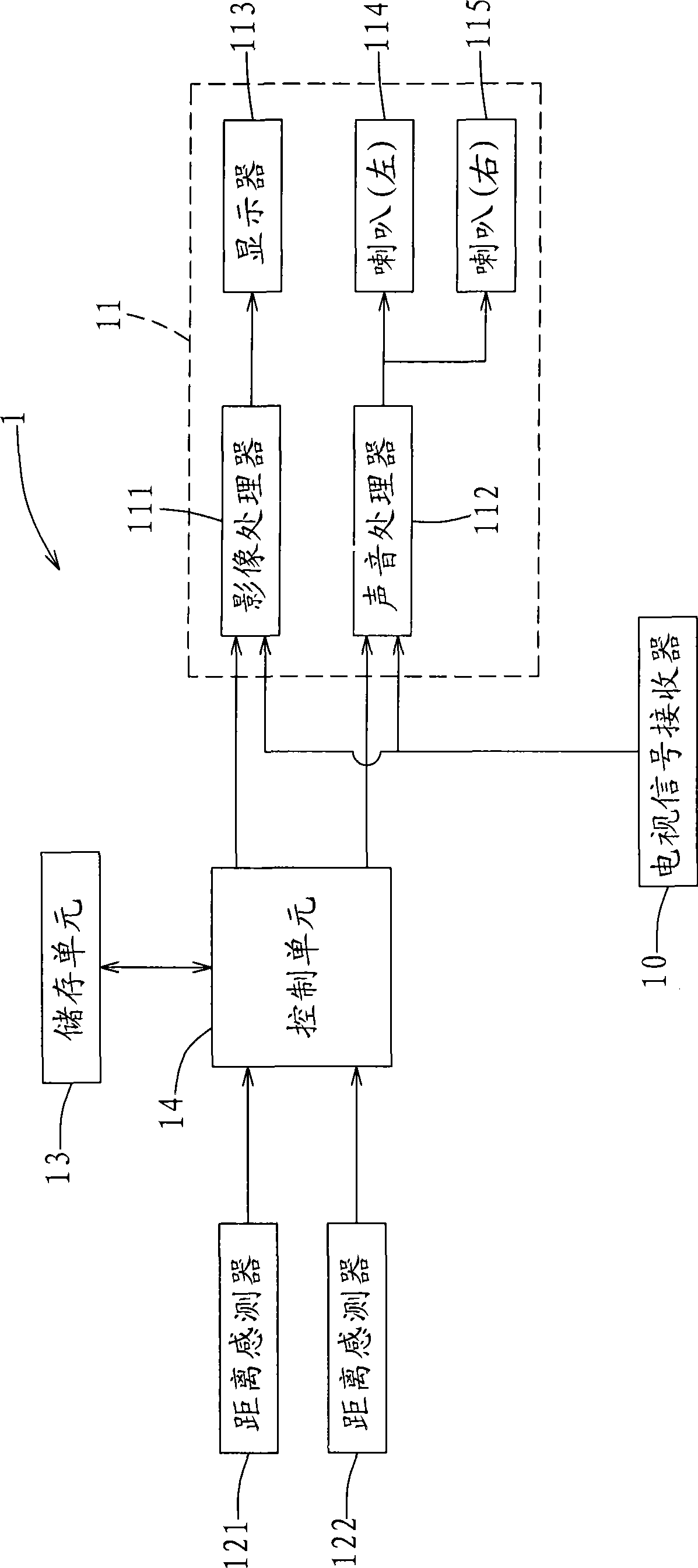
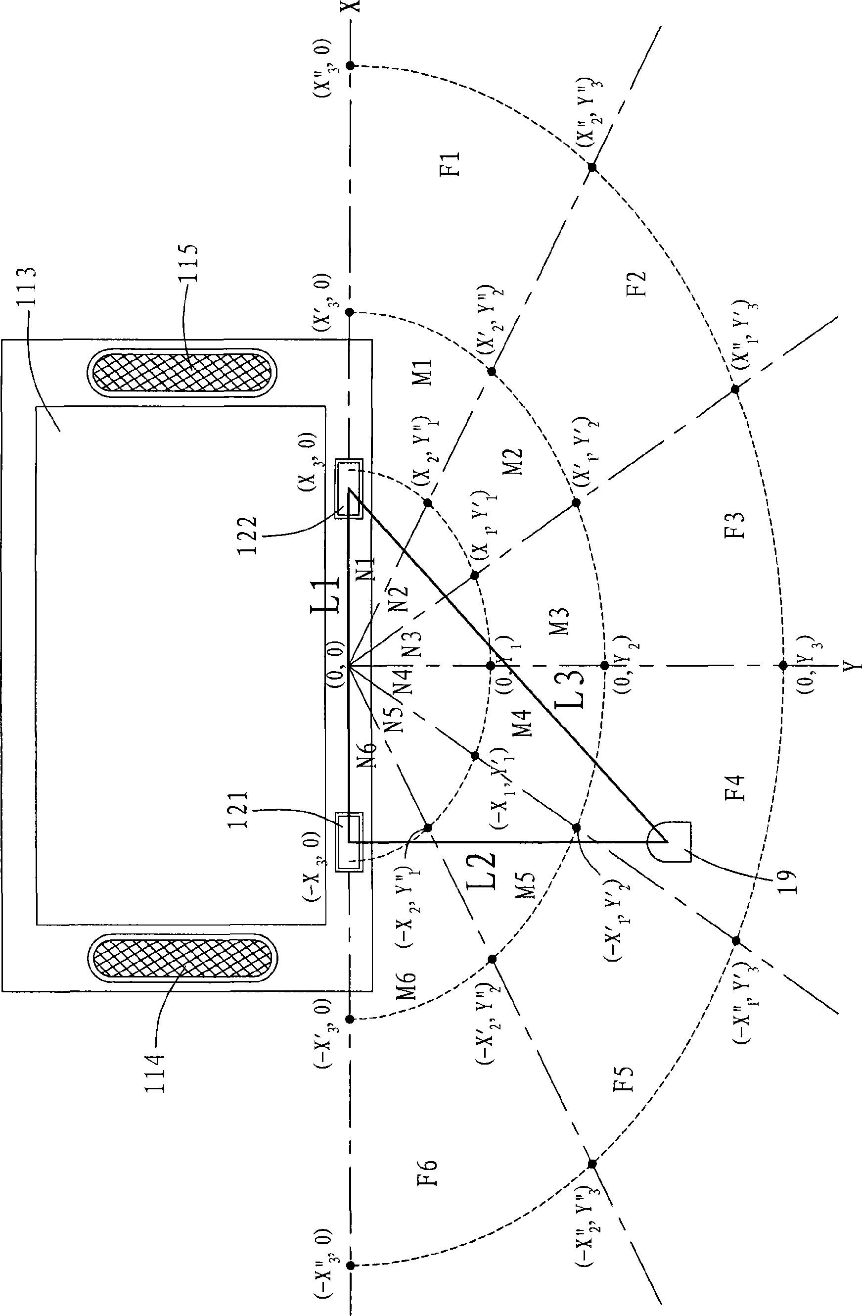
The invention relates to method for adjusting the display effect of a video device according to the position of the viewer and the video device. The method for adjusting the display effect of a video device according to the position of the viewer pre-builds complex in front of video device and the relative position and not far from the same close-up view of the regional coordinate data coordinates of the location of the viewing area table in the video device, receiving a remote control and remote control signals, respectively, and measured the distance between the remote control by the device according to the second video from the distance between the sensor as well as the measured distance with the remote control, get the remote control where the coordinates of the location of the viewing area by the coordinates of the location of the table to find the coordinates of the location of their viewing area, and regional settings should be viewing the video display device at least one parameter, the output of video devices audio and video signals for the coordinates of the location of their viewing area showed a better effect.

Description

technical field [0001] The present invention relates to a method for adjusting the display effect of a video device and the video device thereof, in particular to a method for adjusting the display effect of the video device according to the viewing position of the user, and the video device thereof. Background technique [0002] Existing traditional video devices, such as flat-panel displays or TVs using flat-panel displays, allow users to manually adjust the contrast, brightness, and sharpness of images displayed on their displays according to environmental conditions, but they cannot adjust the brightness and image quality according to the environment. The brightness and the intensity of the radio frequency (image) signal (signal is signal, referred to as signal herein) are used to adjust the image to obtain an enhanced image resolution. [0003] To do this, see figure 1 Shown is a schematic diagram of an image adjustment circuit of a conventional color television. U.S....

Claims


Application Information

Patent Timeline
Patent Type & Authority Applications(China)
IPC IPC(8): H04N5/57G08C23/04
Inventor 徐凡轩黄昭维陈信宇李建纬
Owner ACER INC
Learn More