Video system with intelligent visual display

a video system and visual display technology, applied in the field of video systems, can solve the problems of affecting the the loss of a full view of the scene, and the cost of two camera systems for one field of view is relatively high, and the installation is difficul

Active Publication Date: 2020-05-05
MOTOROLA SOLUTIONS INC
View PDF27 Cites 23 Cited by
  • Summary
  • Abstract
  • Description
  • Claims
  • Application Information

AI Technical Summary

Benefits of technology

[0004]In a preferred embodiment, a video system for intelligent visual display of an object of interest includes a video camera having an imager. The imager produces a first set of image data representing an image of a scene within a field of view of the video camera. The video system also includes video analytics receiving and analyzing the first set of image data to track an object of interest present in the scene. The video analytics generate metadata representing location information corresponding to a location of an image of the object of interest in the image of the scene. The metadata are synchronized to the first set of image data. The video system also includes a display management module receiving the first set of image data and the metadata. The display management module uses the metadata to derive from the first set of image data a second set of image data representing a cropped close-up image of the object of interest. The second set of image data is distinct from the first set of image data to enable separate display presentation of the cropped close-up image of the object of interest and the image of the scene.

Problems solved by technology

The moving parts of PTZ cameras with mechanically driven optics tend to create significant failure and maintenance problems.
The use of mechanically driven optics also results in a loss of a full view of a scene once the camera has zoomed in on an object.
Two camera systems for one field of view are relatively expensive and difficult to install.

Method used


Image

  • Video system with intelligent visual display
  • Video system with intelligent visual display
  • Video system with intelligent visual display

Examples


Embodiment Construction

I. System Overview

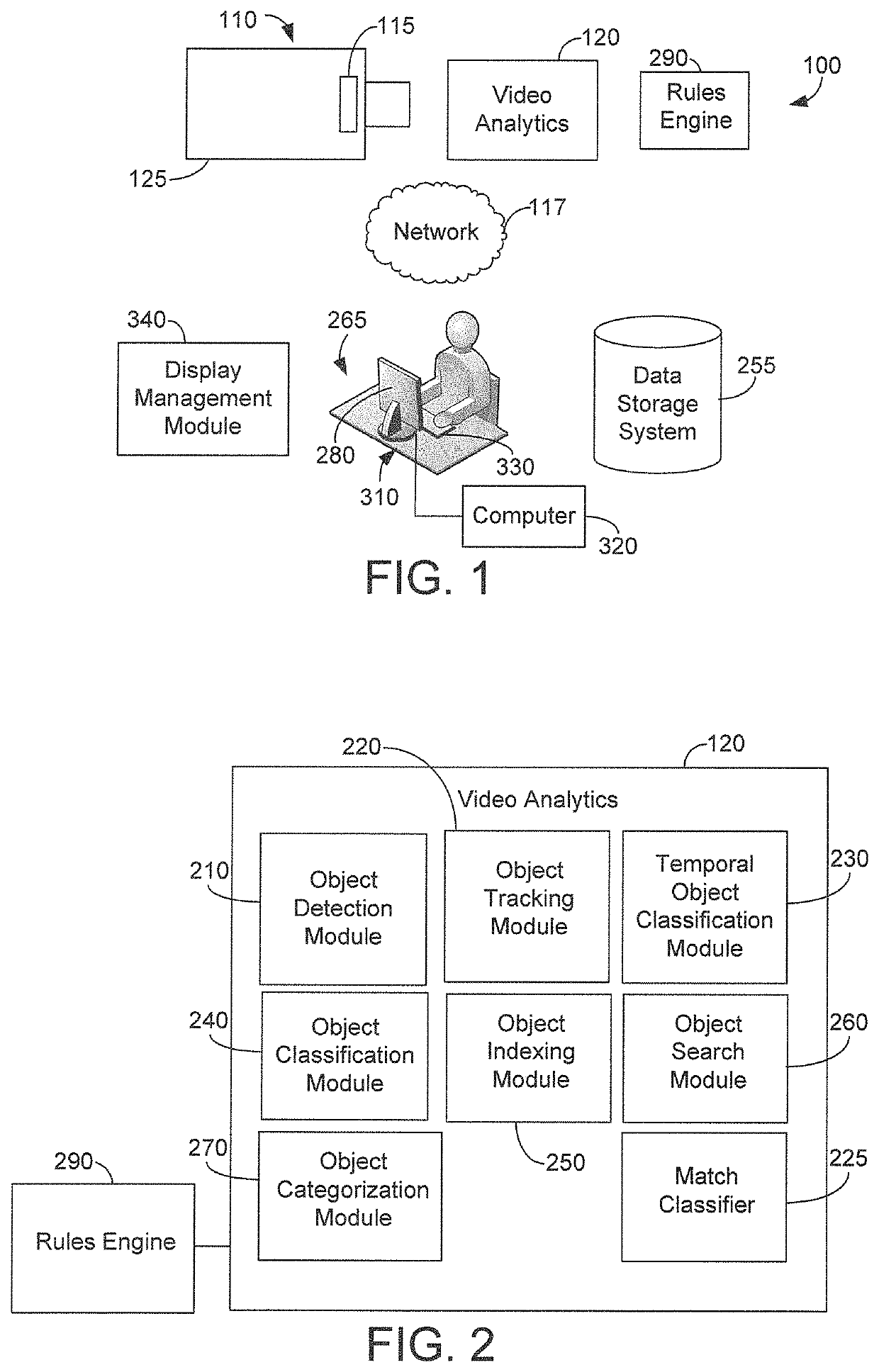
[0020]FIG. 1 is a pictorial diagram of the major components of a camera system 100 according to one embodiment. System 100 includes a video camera 110 and various components for processing image data produced by camera 110. Camera 110 may be any type of video camera. In one example, camera 110 is a network connected camera that is connected to other components of system 100 including other video cameras, if any. Preferably, camera 110 is a megapixel video camera including a high resolution megapixel imager 115 implemented with an advanced pixel architecture for capturing images of a field of view of camera 110. A preferred embodiment of camera 110 accommodates the use of one or more light-sensitive fixed focal length lenses. A fixed focal length, low f-stop lens improves the low-light performance of imager 115. In one example, the video camera described in commonly owned U.S. Patent Application Publication No. 2009 / 0219387, titled “Intelligent High Resolution Video...


PUM


Abstract

A video system for intelligent visual display includes a video camera having an imager that produces a first set of image data representing an image of a scene. Video analytics receive and analyze the first set of image data to track an object. The video analytics generate metadata synchronized to the first set of image data and representing location information of an image of the object in the image of the scene. A display management module receives the first set of image data and the metadata and uses the metadata to derive from the first set of image data a second set of image data representing a cropped close-up image of the object. The second set of image data is distinct from the first set of image data to enable separate display presentation of the cropped close-up image and the image of the scene.

Description

TECHNICAL FIELD[0001]The present disclosure relates to video systems and more particularly to video analytics and video signal processing for use in video surveillance systems.BACKGROUND INFORMATION[0002]Automated security and surveillance systems typically employ video cameras or other image capturing devices or sensors to collect image data. In the simplest systems, images represented by the image data are displayed for contemporaneous screening by security personnel or recorded for later reference after a security breach. In those systems, the task of detecting objects of interest is performed by a human observer. A significant advance occurs when the system itself is able to perform object detection and tracking, either partly or completely.[0003]In a typical surveillance system, for example, one may be interested in tracking a detected object such as a human, a vehicle, or an animal that moves through the environment. Some existing systems include video analytics to automatical...

Claims


Application Information

Patent Timeline
Patent Type & Authority Patents(United States)
IPC IPC(8): H04N7/18G06T7/277G08B13/196G06T7/246
CPCG08B13/19671G06T7/246H04N7/18G08B13/19682G08B13/19608G06T7/277G06T2207/10016G06T2207/30232H04N5/93H04N23/00
Inventor MARMAN, DOUGLAS H.SAPTHARISHI, MAHESHGLOZMAN, LEVIUSHOMIRSKY, MICHAEL
Owner MOTOROLA SOLUTIONS INC
Why Eureka
Try Eureka