Optical attenuator

An attenuator and optical technology, applied in optics, nonlinear optics, instruments, etc., can solve the problems of increasing the cost of digital circuits, increasing the power consumption of circuits, and the limitation of digital circuit clock frequency, so as to improve the resolution level and improve the The effect of power efficiency

Inactive Publication Date: 2011-11-23
TELEFON AB LM ERICSSON (PUBL)
View PDF0 Cites 0 Cited by
  • Summary
  • Abstract
  • Description
  • Claims
  • Application Information

AI Technical Summary

Problems solved by technology

The disadvantage of this circuit is that the power dissipation in the power tube is close to that of the associated thermoelectric element
The traditional way to increase the PWM resolution is to use a higher master clock frequency f clk ; This method will drastically increase the cost of the corresponding digital circuit and increase the operating power consumption of the circuit
Moreover, in practical applications, the clock frequency that digital circuits can achieve is limited.

Method used


Image

  • Optical attenuator
  • Optical attenuator
  • Optical attenuator

Examples


Embodiment Construction

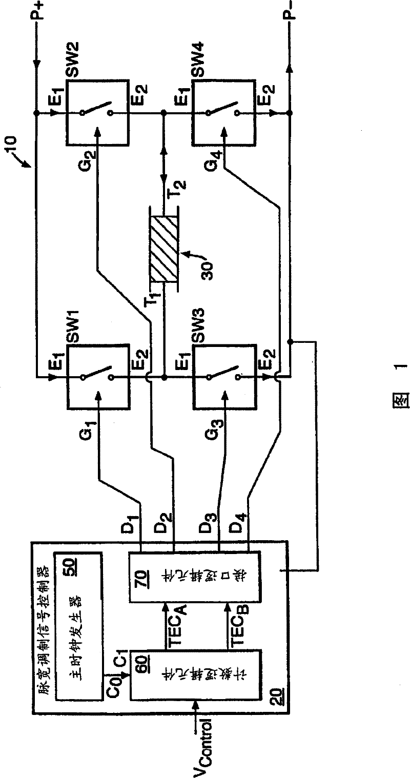
[0051] refer to figure 1 , figure 1 A PWM circuit 10 is shown in FIG. 2 , which is used to control the current entering the Seebeck effect heating element 30 . As will be explained below, heating elements are often used to control the temperature and thus operate electro-optical components such as attenuators, filters or solid-state lasers.

[0052] The circuit 10 comprises a PWM controller 20, and four MOSFET switches SW1, SW2, SW3, SW4. Element 30 is what is known as a "Peltier element". Controller 20 includes a master clock generator 50 , a counter logic unit 60 and an interface logic unit 70 .

[0053] Next, the connection between the various components in the circuit 10 is described, and the interconnection relationship is described in figure 1 middle.

[0054] Each of the switches SW1, SW2, SW3, SW4 comprises a first electrode, a second electrode and an associated gate G. A potential is applied to the gate G to control the current flowing from the first electrode E...


PUM


Abstract

A method of generating a pulse width modulated (PWM) signal comprises: receiving digital demand data V<control> comprising at least one more significant bit (bit>7< to bit 14>) and at least one less significant bit (bit0 to bit6). The PWM signal comprises a sequence of one or more frames (100), each frame: comprising a plurality of PWM pulses (W1 to W127) whose duty cycle is substantially governed by the at least one more significant bit (bit7 to bit14); and having at least one of its PWM pulses selected to have its duty cycle modified in response to the at least one less significant bit (bit0 to bit6); each of the at least one less significant bit (bit0 to bit6) uniquely mapping onto the at least one selected PWM pulse of the frame (100). The invention is also concerned with apparatus operable according to the above method and an optical attenuator whose optical attenuation is dependent upon its temperature and in which the temperature an hence attenuation is controlled using the above PWM signal.

Description

[0001] This application is a divisional application of the following international invention patent application submitted on March 23, 2001, international application number: PCT / GB01 / 01309, national application number: 01807041.8, invention name: "Method for generating pulse width modulation signal and devices and optical attenuators controlled by pulse width modulated signals” technical field [0002] The present invention relates to a method and apparatus for generating a pulse width modulated (PWM) signal. More specifically, the present invention relates to temperature control of electro-optical components, such as attenuators, filters, and solid-state lasers. These elements are used in optical communication systems. Also, although not exclusively, the present invention generally relates to an optical attenuator with enhanced resolution for use in an optical communication system. Background technique [0003] In traditional optical communication systems, optical attenu...

Claims


Application Information

Patent Timeline
Patent Type & Authority Patents(China)
IPC IPC(8): G02F1/01
CPCG02F2203/48G02F1/0147G02F1/0121
Inventor R・W・布朗E・A・丹尼斯D・W・瓦斯G・布特勒M・J・利奇
Owner TELEFON AB LM ERICSSON (PUBL)
Why Eureka
Try Eureka