
Reduction of tonal noise in cooling fans using splitter blades

A technology of splitter blades and fans, which is applied to parts of pumping devices for elastic fluids, liquid fuel engines, machines/engines, etc., can solve the problems of low frequency component amplitude and less obvious comparison, and achieve discrete noise Reduced effect

Inactive Publication Date: 2008-12-17
MINEBEA CO LTD
View PDF0 Cites 6 Cited by
  • Summary
  • Abstract
  • Description
  • Claims
  • Application Information

AI Technical Summary

Problems solved by technology

Broadband noise is another noise component, but it is less pronounced than discrete noise because its spectrum is usually much wider than that of discrete noise and its frequency components have lower amplitudes

Method used


Image

  • Reduction of tonal noise in cooling fans using splitter blades
  • Reduction of tonal noise in cooling fans using splitter blades
  • Reduction of tonal noise in cooling fans using splitter blades

Examples


Embodiment Construction

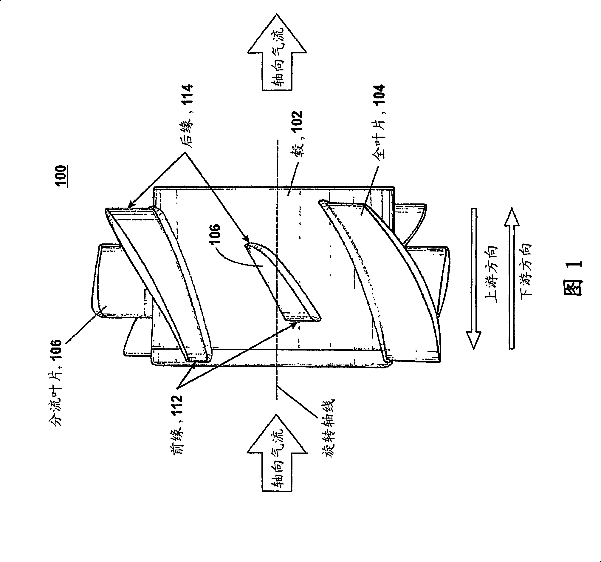
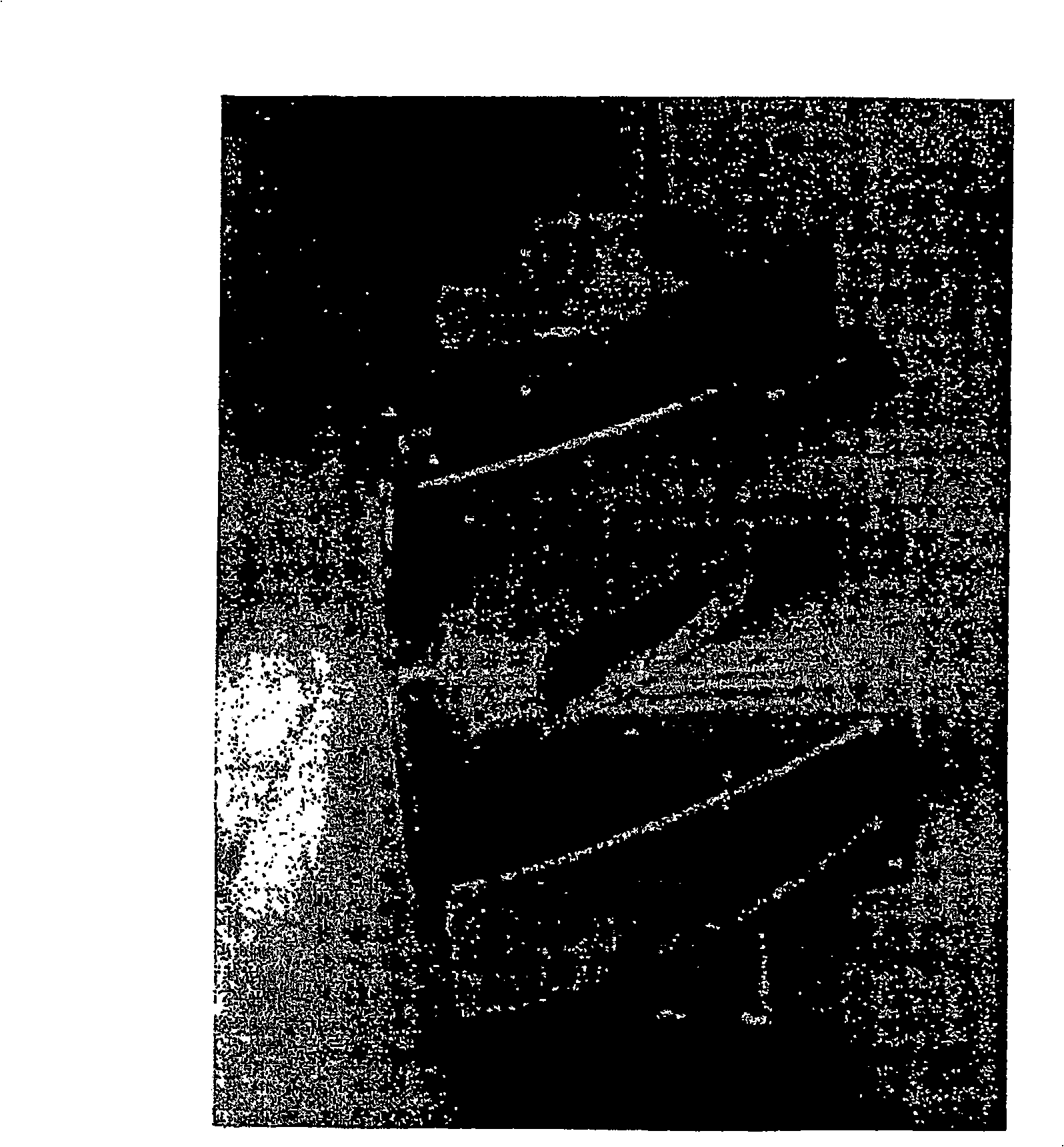
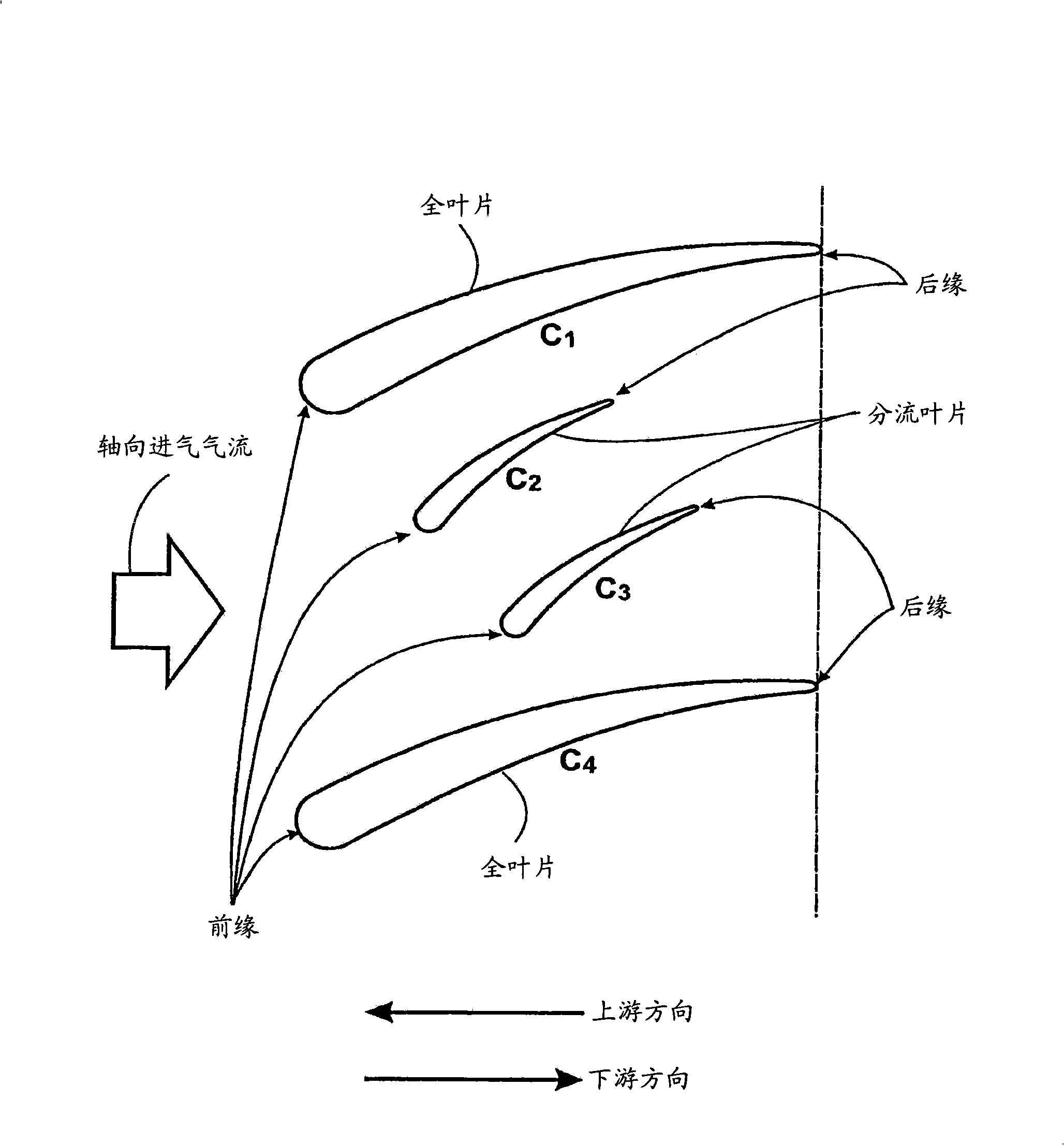
[0014] Figure 1 shows an axial flow impeller 100 made in accordance with the teachings of the present invention. Figure 1A is a photo of the impeller prototype shown in Figure 1. The impeller includes a hub 102 . A plurality of fan blades 104 , 106 are arranged around hub 102 . This figure shows what is commonly referred to as a "full blade" 104 . Disposed between a pair of full blades 104 is a blade called a "splitter blade" 106 . The blades 104, 106 are connected to the hub 102 at the roots of the blades. As the impeller 100 rotates about its axis of rotation, an axial flow is created, as indicated by the arrows. According to the invention, the splitter blades 106 in FIG. 1 are connected to the hub 102 so that their axial position relative to the full blades falls between the leading edge 112 and the trailing edge 114 of these full blades 104 . This will be in figure 2 discussed in detail.

[0015] Referring now to Figure 5, a detailed description of a cross-sectiona...


PUM


Abstract

Disclosed is a hub of an axial fan. The hub includes primary fan blades and splitter blades disposed between pairs of the primary fan blades. The resulting hub has been observed to reduce tonal noise during fan operation.

Description

[0001] Related Application Cross Reference [0002] This application claims priority to US Provisional Application No. 60 / 755,474, filed December 29, 2005, which is hereby incorporated by reference in its entirety. technical field [0003] The present invention relates generally to axial fans, and in particular to a configuration of fan blades to reduce noise. Background technique [0004] FIG. 4 shows an exploded cross-sectional view of components constituting a conventional axial fan. Shown is the base 402, which is part of the cooling fan housing (not shown), on which the stator is mounted. Typically, the base 402 includes a small printed circuit board used in the electronics for controlling the operation of the motor. Power and control wires (not shown) emerge from the printed circuit board for connection to an external power source and computer. The stator assembly includes a coil assembly 404 comprising individually fired coils wound around a bushing 406 . The roto...

Claims


Application Information

Patent Timeline
Patent Type & Authority Applications(China)
IPC IPC(8): B64C11/16
CPCF04D29/665F04D29/384F04D29/526F05B2260/96
Inventor 优素福·贾拉约翰·赫茨贝格尔德斯蒙德·里德尔
Owner MINEBEA CO LTD
Learn More