

Image forming apparatus
An image and image bearing technology, which is applied in the electrical recording process using charge patterns, the equipment of the electrical recording process applying charge patterns, and electrical recording techniques, can solve problems such as balance damage, change the driving time, and reduce the difference. , the effect of good stirring or electrification
- Summary
- Abstract
- Description
- Claims
- Application Information
AI Technical Summary
Problems solved by technology
Method used
Image

Examples
no. 1 example
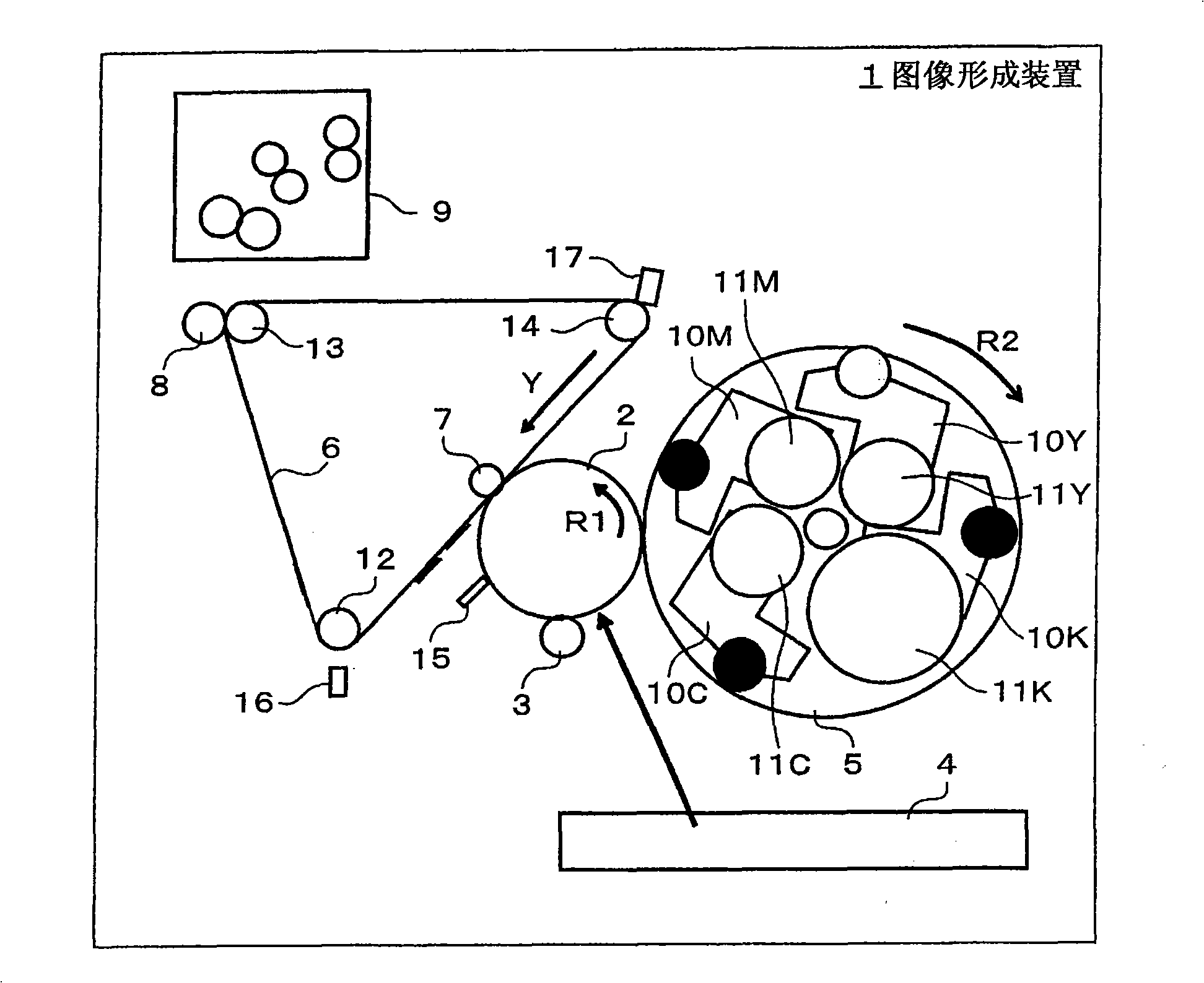
[0059] figure 1 is a schematic diagram showing an example of the overall configuration of an image forming apparatus according to an embodiment of the present invention. Image forming apparatus 1 includes image bearing member 2 , charging device 3 , exposure device 4 , rotary developing device 5 , intermediate transfer member 6 , primary transfer device 7 , secondary transfer device 8 , and fixing device 9 .
[0060] During the image forming operation, the image bearing member 2 rotates at a constant peripheral speed along the R1 direction. The image bearing member 2 is configured from a photosensitive drum. The charging device 3 charges the surface (periphery) of the image bearing member 2 to a predetermined potential level. The exposure device 4 forms an electrostatic latent image on the surface of the image bearing member 2 charged to a predetermined potential level, for example, by scanning exposure of laser light.
[0061] The rotary developing device 5 develops the el...
no. 2 example
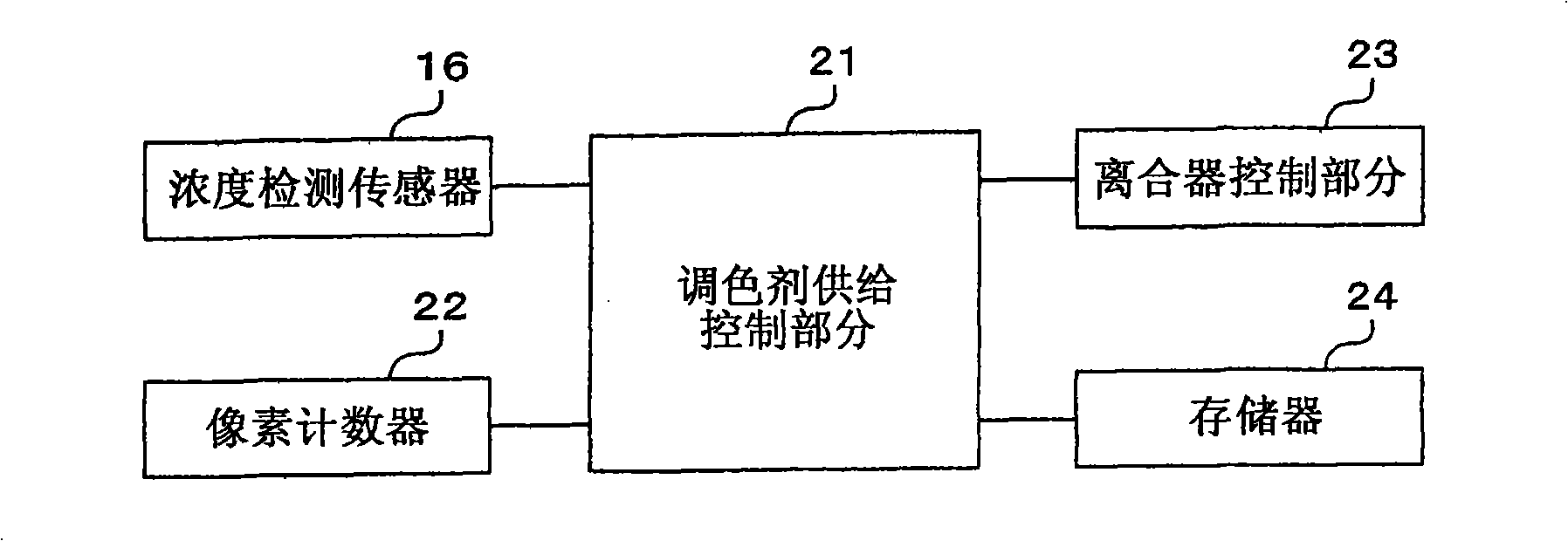
[0121] Figure 5 is a flowchart showing the procedure of the toner supply control process according to the second embodiment of the present invention. This processing flow is applied to the case of performing the above-described toner supply buffer processing. First, the toner supply control section 21 judges whether the processing speed notified from the image formation control section (not shown) is set to "high speed" or "middle speed" or "low speed" (step S11).
[0122] When it is judged in step S11 that the processing speed is set to "high speed", the coefficient M11 stored in the memory 24 corresponding to the processing speed of "high speed" is read (step S12). When it is judged that the processing speed is set to "medium speed", the coefficient M12 corresponding to the processing speed of "medium speed" stored in the memory 24 is read (step S13). When it is judged that the processing speed is set to "low speed", the coefficient M13 corresponding to the processing spe...
no. 3 example
[0148] FIG. 9 is a schematic diagram showing an example of the overall configuration of an image forming apparatus according to an embodiment of the present invention. An image forming apparatus 1001 adopts a four-wheel tandem machine configuration and includes four image forming sections 1002, 1003, 1004, and 1005, an exposure device 1006 common to the four image forming sections 1002, 1003, 1004, and 1005, an intermediate transfer member 1007, and two Secondary transfer device 1008 .
[0149] The image forming apparatus 1001 forms a full-color image using four color toners of yellow, magenta, cyan, and black in the multi-color image forming mode, and forms a black-and-white image using black toner in the monochrome image forming mode. . The image forming section 1002 forms a visible image using yellow toner, and the image forming section 1003 forms a visible image using magenta toner. In addition, the image forming section 1004 forms a visible image using cyan toner, and t...
PUM
 Abstract
Description
Claims
Application Information