
Method for producing optical element

A technology for optical components and manufacturing methods, applied to optical components, other household appliances, household appliances, etc., can solve the problem of low degree of freedom of lens forming, achieve the effect of preventing ghosting or flare, and improving the degree of freedom of forming

Inactive Publication Date: 2009-01-28
ALPS ALPINE CO LTD
View PDF1 Cites 0 Cited by
  • Summary
  • Abstract
  • Description
  • Claims
  • Application Information

AI Technical Summary

Problems solved by technology

That is, the degree of freedom in molding the lens portion of the substrate having the light-shielding film is low.

Method used


Image

  • Method for producing optical element
  • Method for producing optical element
  • Method for producing optical element

Examples


Embodiment Construction

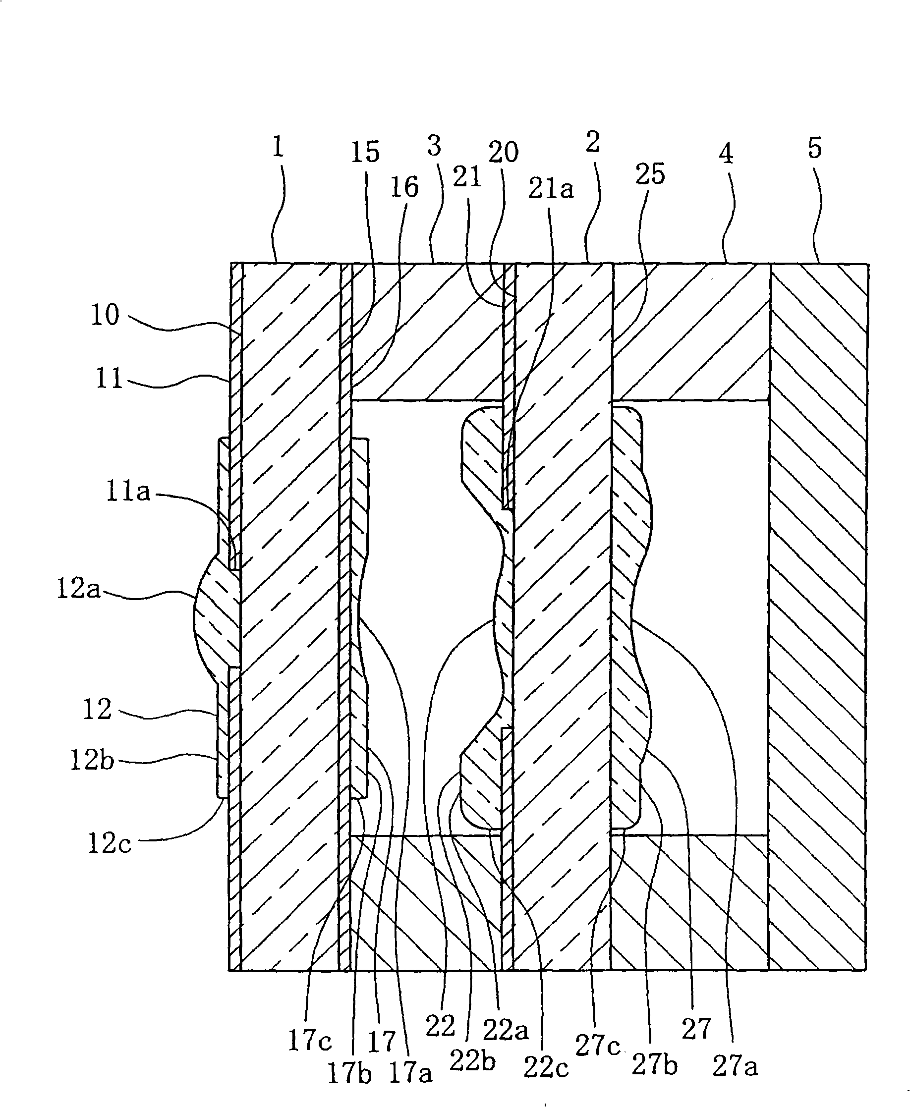
[0025] Embodiments of the present invention will be described in detail below using the drawings. figure 1 In , a cross-sectional view of the optical element of this embodiment is shown. As shown in the figure, in the optical element of the present embodiment, the first transparent substrate 1 and the second transparent substrate 2, which are made of transparent glass and have a lens portion on the surface, face each other through the first spacer 3, and the second The transparent substrate 2 faces the light receiving unit 5 with the second spacer 4 interposed therebetween. As a result, light rays incident from the first transparent substrate 1 side pass through the lens portions respectively formed on the surfaces of the first transparent substrate 1 and the second transparent substrate 2 , and converge on the light receiving portion 5 .

[0026] On the surface of the first surface 10 of the first transparent substrate 1, the first light-shielding film 11 is adhered. The op...


PUM


Abstract

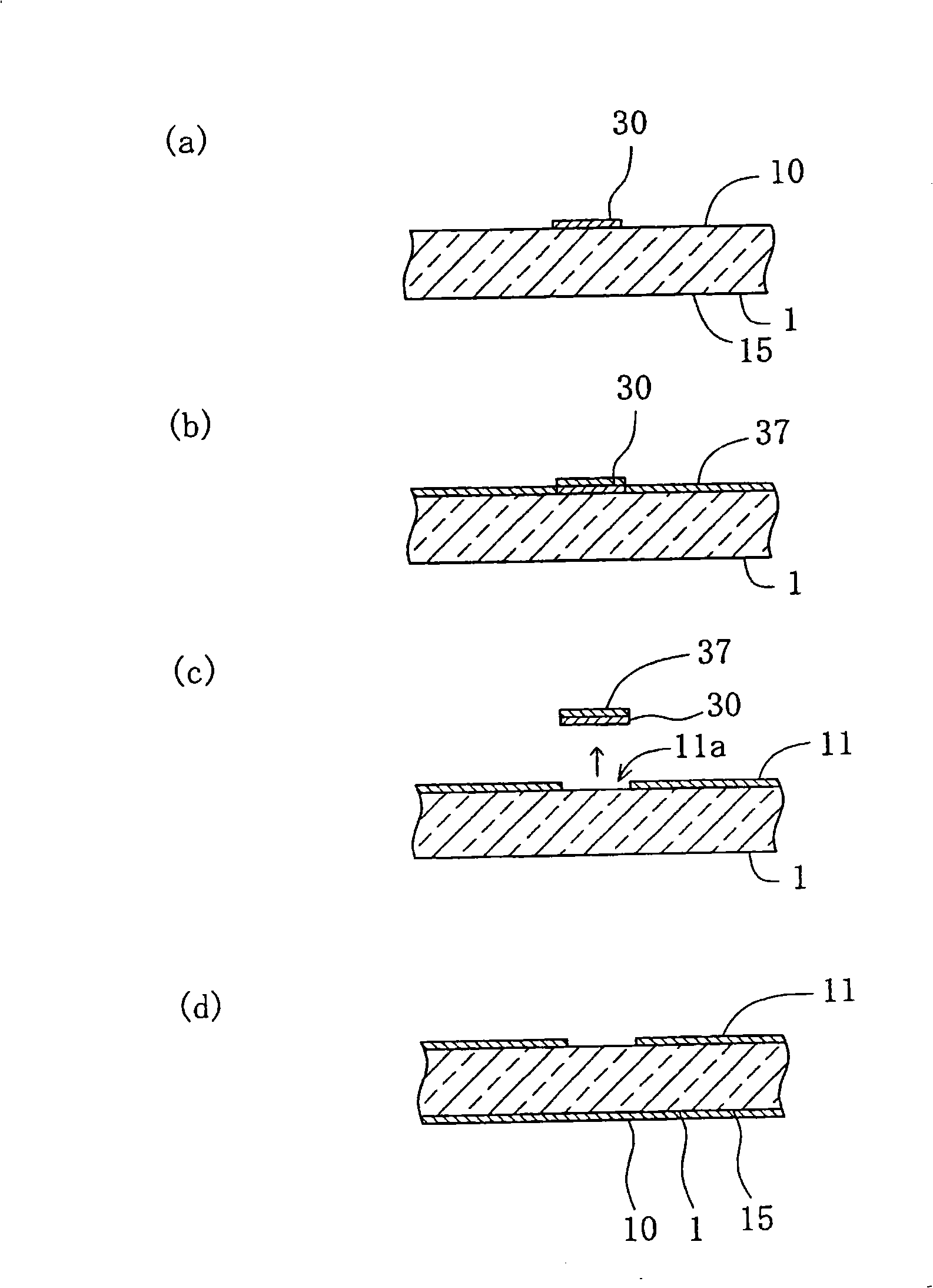
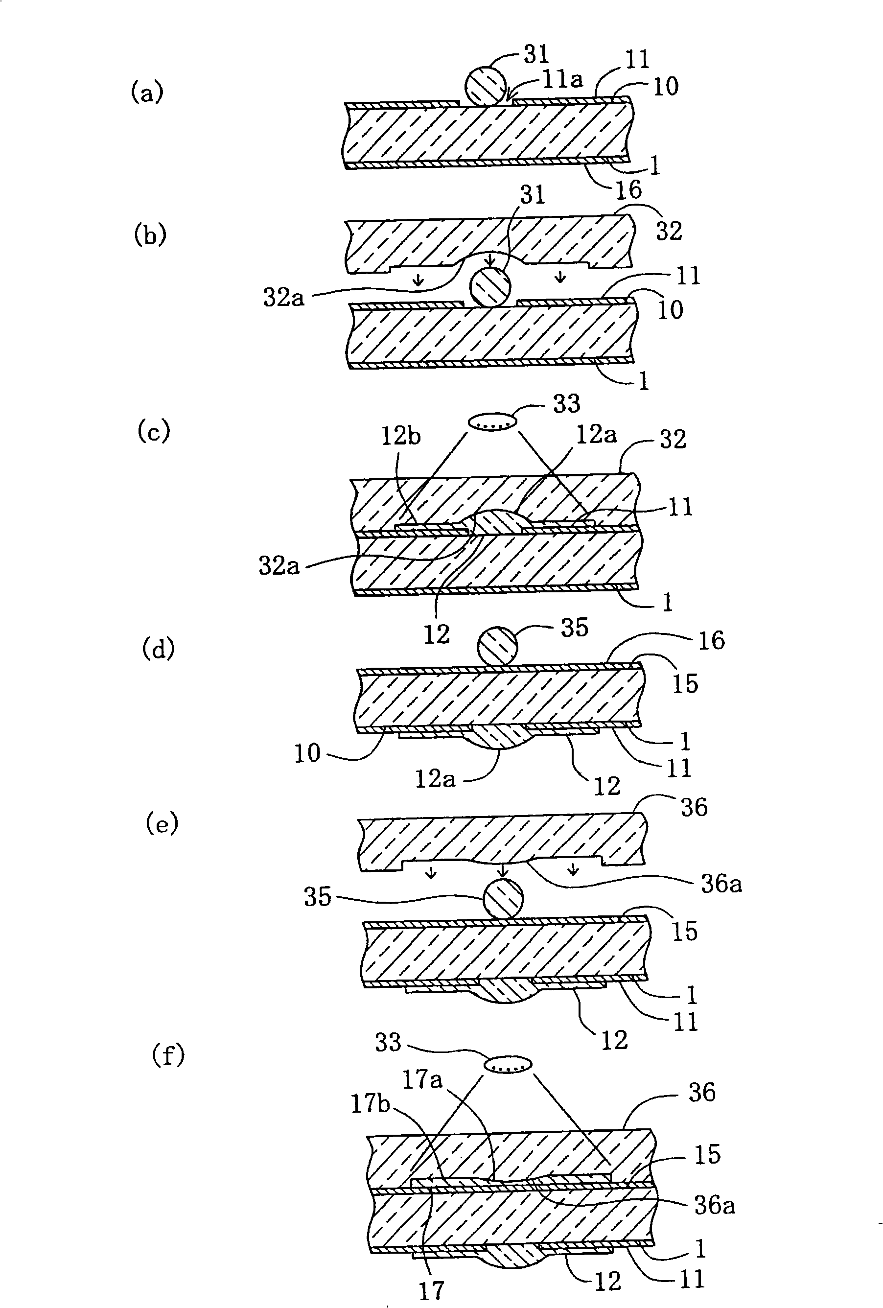
The invention provides a manufacturing method for an optical element that can form a lens portion quite freely on a substrate having a shading capsula. The manufacturing method is for the optical element that is constituted by forming the lens portion (12) on the substrate (1) a surface of which is formed with a light-permeable opening portion (11), a resin material (31) made of ultraviolet hardened resin is carried at the position of the opening portion (11) of the substrate (1) in order that a die (32) having a lens forming surface (32a) and made of ultraviolet-permeable material presses the resin material (31), and under the pressing state, the ultraviolet-permeable die (32) irradiates and hardens the resin material (31) to form the lens portion (12) on the surface of the substrate (1).

Description

technical field [0001] The present invention relates to a method of manufacturing an optical element formed by forming a lens portion on a surface of a substrate, and more particularly to a method of manufacturing an optical element having an opening serving as a diaphragm formed on the surface of the substrate. Background technique [0002] As an optical element having a lens portion used in a camera or the like, there is conventionally known a configuration in which the lens portion is formed on the surface of a transparent substrate made of glass, resin, or the like. The lens part is provided with a lens functional surface functioning as a lens on the surface, so as to perform the function of concentrating light. It is also known to use an ultraviolet curable resin as a material of the lens portion in order to efficiently form the lens portion in an array on a transparent substrate. [0003] In this case, after mounting the uncured ultraviolet curable resin on the upper ...

Claims


Application Information

Patent Timeline
Patent Type & Authority Applications(China)
IPC IPC(8): B29C43/02B29C35/08B29L11/00
Inventor 荻荘重之神山浩一京谷升一筱原英司高村章三
Owner ALPS ALPINE CO LTD
Learn More