Laryngoscope blade

A kind of technology of laryngeal blade and blade end

Inactive Publication Date: 2009-02-04
AIRCRAFT MEDICAL LTD
View PDF0 Cites 11 Cited by
  • Summary
  • Abstract
  • Description
  • Claims
  • Application Information

AI Technical Summary

Problems solved by technology

This means that image capture and / or illumination devices are offset from the target site and therefore must be tilted towards the target site, which can add complexity and cost, and often results in a more extensive assembly procedure

Method used


Image

  • Laryngoscope blade
  • Laryngoscope blade
  • Laryngoscope blade

Examples


Embodiment Construction

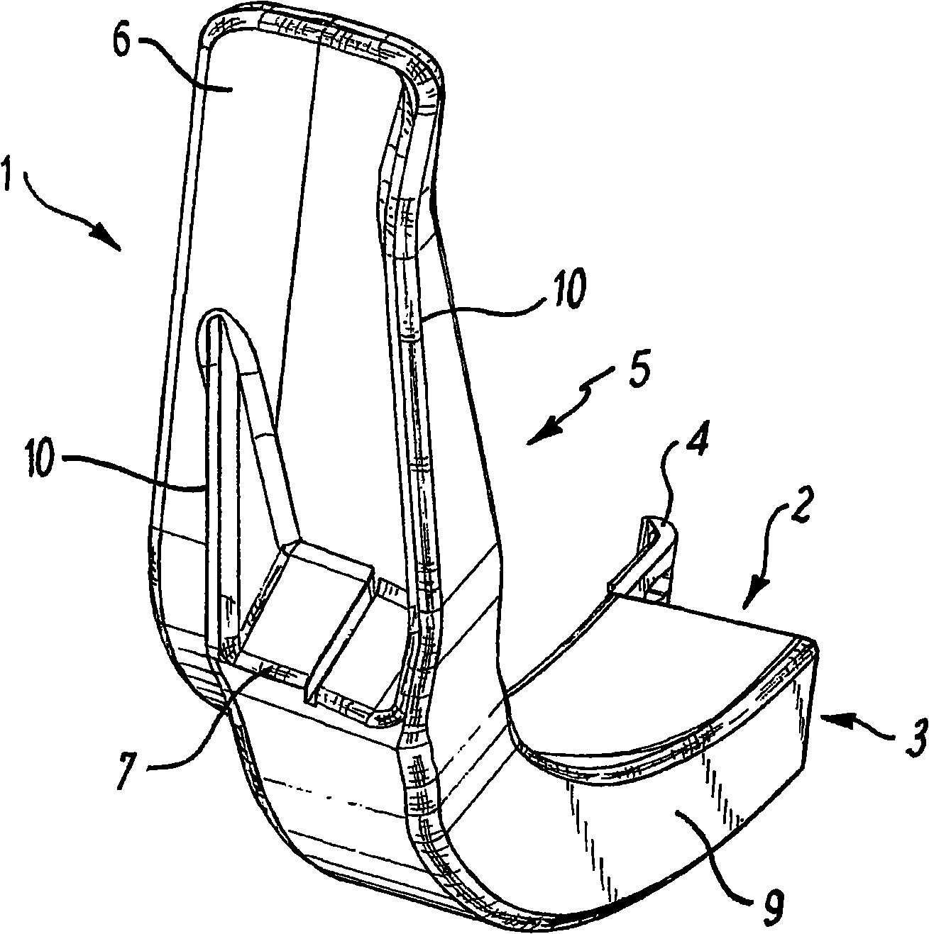
[0043] figure 1 Shown is a laryngeal lens 1, which includes an opening 2, a handle 3 and a lens end 5. The handle 3 has a connecting device 4 to connect the sheath type laryngeal lens 1 to the laryngoscope, and the lens end 5 has a tip 6.

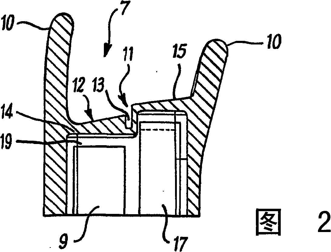
[0044] The laryngeal lens 1 includes a channel 9 extending from the handle 3 to the end surface 7. Both sides of the end face are provided with end face supporting members 10 to improve the structural strength of the laryngeal lens. The channel 9 is suitable for the insertion of an image capture device and / or a lighting device.

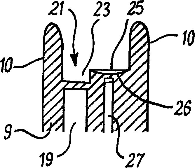
[0045] FIG. 2 is a cross-sectional view of the end face 7. The end surface includes an optical element 11 for receiving light from the light source 17. The optical element 11 includes a prism 15 and is bounded by a gap or channel 13, which separates the optical element 9 from the second optical element 12, which is adapted to receive the patient’s throat (or other The relevant part of the camera 19) reflects the ligh...


PUM


Abstract

A laryngoscope blade improves the transmission of light from the laryngoscope to enhance the amount of light reflected from an area of interest in a patient. The laryngoscope blade has a channel which extends at least partially though the blade and receives a light source. The channel has a substantially transparent end face which is situated towards the blade end and has an optical element adapted to reduce the ambient light signal from the light source in the channel.

Description

Technical field [0001] The present invention relates to a sheath type laryngoscope, in particular to a laryngoscope lens used in the laryngoscope, including a disposable laryngoscope lens. Background technique [0002] Laryngoscope is a device used by doctors to open the patient's airway during tracheal intubation. An important point in using a laryngoscope is that the doctor must be able to distinguish the vocal cords and surrounding tissue structures when inserting the laryngoscope. In many cases, this is done by looking directly at the patient’s mouth to visually identify the larynx area, or by placing a camera on or in the middle of the laryngeal lens and observing that part on the screen. [0003] Usually, a light source is installed outside the non-disposable laryngeal lens. In addition, some disposable laryngeal lenses include sheath-type laryngeal lenses, which have a transparent part through which light penetrates the patient's throat from the end surface. The light is i...

Claims


Application Information

Patent Timeline
Patent Type & Authority Applications(China)
IPC IPC(8): A61B1/267G02B23/26
Inventor M·麦格拉斯
Owner AIRCRAFT MEDICAL LTD
Why Eureka
Try Eureka