
Steering locking device

A technology for locking devices and locking positions, applied in anti-theft locks, building locks, vehicle locks, etc., can solve the problem of illegally maintaining the non-engaging position of auxiliary locking components, and achieve the effect of preventing illegal unlocking

Inactive Publication Date: 2012-08-15
U SHIN LTD
View PDF1 Cites 0 Cited by
  • Summary
  • Abstract
  • Description
  • Claims
  • Application Information

AI Technical Summary

Problems solved by technology

[0007] However, in this auxiliary locking mechanism, since the auxiliary locking member engaged with the lock bolt can be operated by inserting a thin rod-shaped member into the through hole, there is a possibility that the auxiliary locking member is illegally maintained at the disengaged position.

Method used


Image

  • Steering locking device
  • Steering locking device
  • Steering locking device

Examples


Embodiment Construction

[0022] Hereinafter, embodiments of the present invention will be described based on the drawings.

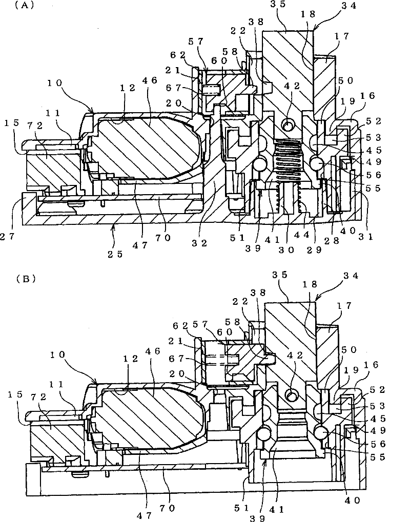
[0023] figure 1 (A), (B) to Figure 4 A steering lock device (hereinafter referred to as a "lock device") according to an embodiment of the present invention is shown. The lock device is arranged around a steering shaft that rotates with a turning operation of a steering wheel (not shown), and operates in conjunction with a button switch for starting or stopping the engine and a card-key operation. In addition, similar to the prior art, an engagement recess is formed at a predetermined position in the circumferential direction of the steering shaft.

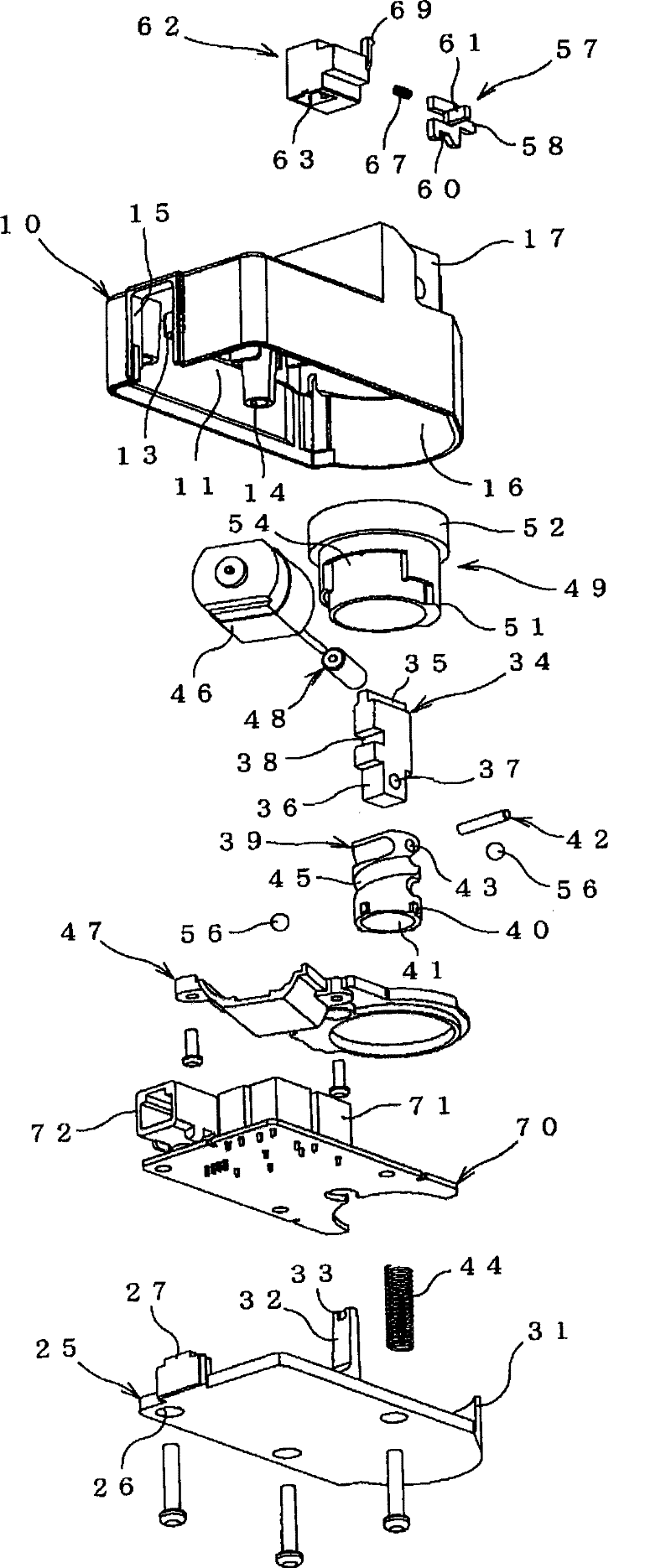
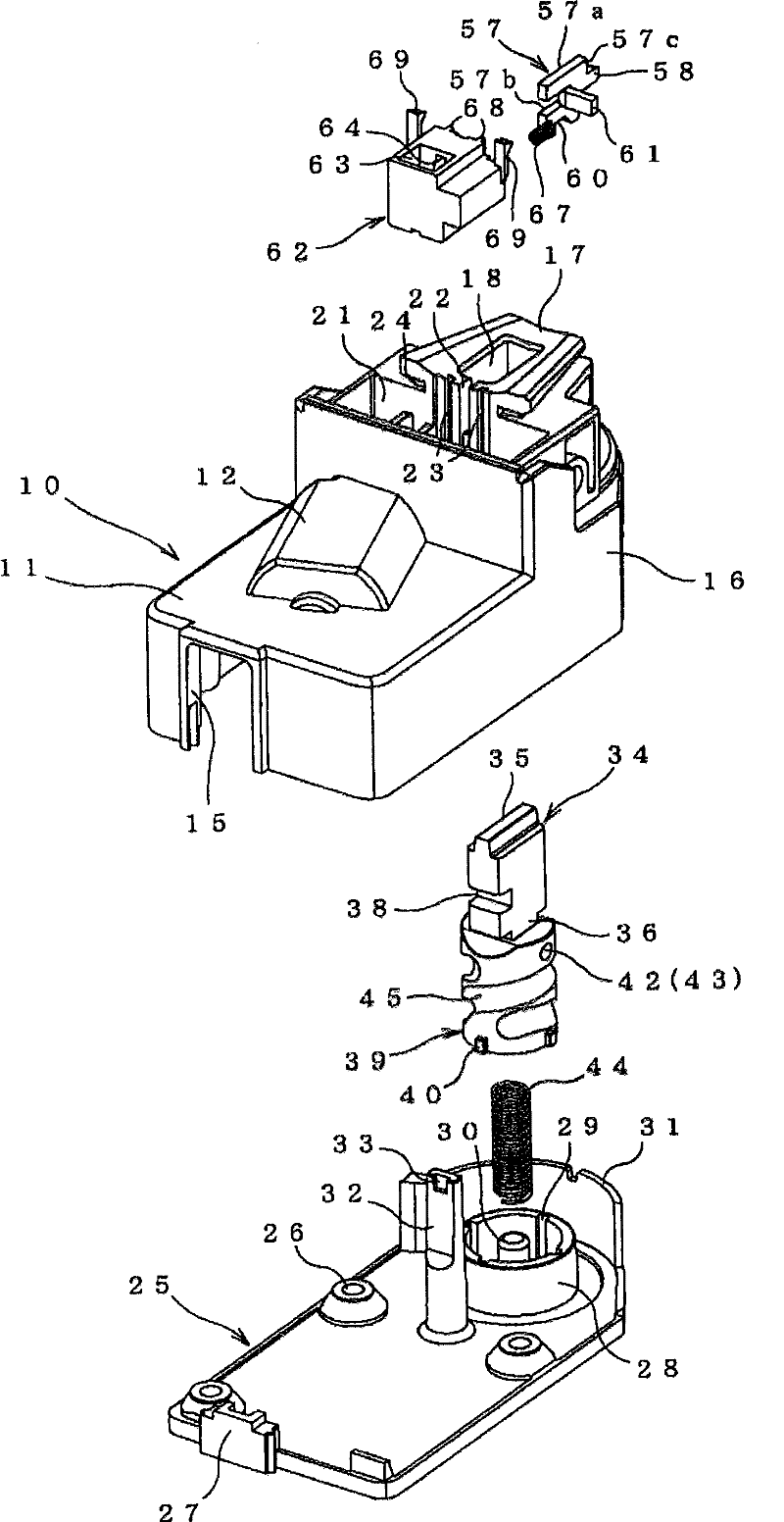
[0024] The lock device of the present embodiment includes a box body 10 and a box body cover 25 with one end opened. Inside the space formed by the box body 10 and the box body cover 25, a lock bolt 34, a motor 46 as an actuator, a transmission mechanism, and an auxiliary lock mechanism that restricts forward and backward movement of t...


PUM


Abstract

The invention provides a steering locking device capable of reliably preventing the illegal unlocking. The box body (10) is provided with a communicating pore (20) extending along the installation direction of the box body cover (25); and the front end of the cover installation direction of the communicating pore (20) is configured with an auxiliary locking component (57); the auxiliary locking component (57) can move from the locked bolt (34) blocked at the locking position not the blocking position operated by the communicating pore (20) to the non-blocking position blocked with the locked bolt (34) and operated by the communicating pore (20); the box body cover (25) is provided with a blocking protuberance (32) communicating with the communicating pore (20) of the box body (10) and blocked with the auxiliary locking component (57) at the non-blocked position to keep the auxiliary locking component (57) cannot move.

Description

Technical field [0001] The invention relates to a steering lock device for vehicle steering lock. Background technique [0002] A conventional steering lock device for vehicle steering lock for the purpose of preventing theft is provided with an engagement recessed portion on the outer periphery of a steering shaft that rotates with a steering operation. When the driver uses a key or the like to stop the engine of the vehicle, a lock bolt that can advance and retreat enters and engages with the engagement recess, thereby restricting the rotation of the steering shaft and locking the steering. On the other hand, when the driver uses the key to start the engine, the lock bolt moves backward from the engagement recess to release the engagement, thereby releasing the rotation restriction of the steering shaft and unlocking the steering. [0003] In addition, when the lock bolt enters the lock operation on the steering shaft side, the engagement recess of the steering shaft often does ...

Claims


Application Information

Patent Timeline
Patent Type & Authority Patents(China)
IPC IPC(8): B60R25/02E05B17/20B60R25/0215E05B77/44E05B83/00
CPCB60R25/02153
Inventor 谷冈大辅
Owner U SHIN LTD
Learn More