

Drive circuit for high speed switch tube floating grid
A floating gate, driving circuit technology, applied in circuits, electronic switches, transistors, etc., can solve the problems of narrow working linear region, difficult application of circuits, and difficult circuit adjustment, so as to increase the flexibility of circuit design and facilitate a wide range of applications. Application, the effect of low circuit cost
Inactive Publication Date: 2010-11-24
深圳市圣美歌科技有限公司
View PDF0 Cites 0 Cited by
- Summary
- Abstract
- Description
- Claims
- Application Information
AI Technical Summary
Problems solved by technology
The requirements of high withstand voltage and high speed pose a great challenge to the existing semiconductor technology, so this kind of circuit is difficult to apply in the occasion where the operating voltage difference between the driving circuit and the MOSFET exceeds 1000V
(4). The solution shown in Figure 1 is usually implemented by an ASIC (mainly the IR21xx series of IR Company), which makes it difficult for engineers to make targeted adjustments to the circuit according to actual application conditions.
Since this drive circuit uses transformer coupling, the operating frequency, voltage amplitude, and duty cycle of the gate drive are all limited by the properties of the transformer's magnetic material
This makes its working linear region very narrow, which can only be applied to occasions with specific frequency, specific amplitude, and small change in duty cycle, and cannot meet the requirements of most floating gate drive circuits.
Moreover, in order to adjust the rising edge speed of the MOSFET drive, there are the same disadvantages as the bootstrap capacitive floating gate drive circuit
Method used
View moreImage
Smart ImageViewing Examples

Examples
Embodiment Construction
Login to View More PUM
 Abstract
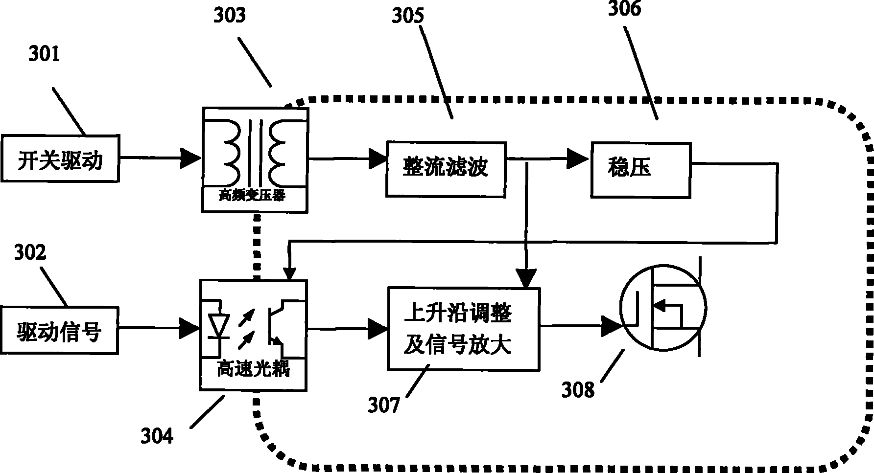
The invention relates to a high speed switching tube floating grid driving circuit, aiming at solving the technological problem of the existing switching tube floating grid driving circuit that duty ratio is limited, and the like. In the invention, the source electrode of MOSFET or the emitter of IGBT is taken as a floating ground, a driving signal is processed to be the driving signal based on the floating ground by high-speed optical coupling; a high frequency transformer driven by a switching signal provides a floating power supply and supplies power to a rising edge regulating and signal amplifying circuit by a rectification filter circuit, and also supplies power to an optical coupling circuit by a voltage stabilizing circuit. The rising edge regulating and signal amplifying circuit can output a floating driving signal based on the floating ground and with adjustable rising edge speed. The invention realizes the floating grid driving circuit, the duty ratio of which can reach 100percent for a long term, the switching tube driving signal rising speed is adjustable inside the driving circuit, voltage difference between the signal ground and the floating ground of the floating grid driving circuit can be improved to 2500V, and the circuit has low cost and is convenient for wide application.
Description
High-speed switching tube floating gate drive circuit technical field The invention relates to a high-speed switching tube floating gate drive circuit, more specifically, to a high-speed switching tube floating gate drive circuit using an optocoupler, which can be used in the fields of switching power supplies, class D audio amplifiers, and the like. The switch tube may be a MOSFET (Metal Oxide Semiconductor Field Effect Transistor) or an IGBT (Insulated Gate Bipolar Transistor). Background technique In the fields of switching power supplies, class D audio amplifiers, etc., it is often encountered that N-channel MOSFETs or IGBT switching tubes need to be driven by floating gates. The following uses MOSFETs as an example to illustrate. Since the source level of the MOSFET in these occasions is usually a complex waveform, and the turn-on condition of the MOSFET is to provide a stable voltage between the gate and the source, the gate of the MOSFET in this case needs to be dri...
Claims
Login to View More Application Information
Patent Timeline
 Patent Type & AuthorityPatents(China)
IPC IPC(8): H03K17/687H03K17/60H03K17/04
Inventor卫强
Owner深圳市圣美歌科技有限公司