Controllable high-rise escaper

An escape device and high-rise building technology, applied in life-saving equipment, building rescue and other directions, can solve problems such as poor safety and difficult operation, and achieve the effects of easy operation, low cost and strong practicability

Active Publication Date: 2011-06-15
CHANGCHUN UNIV OF TECH +2
View PDF4 Cites 2 Cited by
  • Summary
  • Abstract
  • Description
  • Claims
  • Application Information

AI Technical Summary

Problems solved by technology

[0003] The invention provides a controllable high-rise escape device to solve the problems of poor safety and difficult operation of existing equipment

Method used


Image

  • Controllable high-rise escaper
  • Controllable high-rise escaper
  • Controllable high-rise escaper

Examples


Embodiment Construction

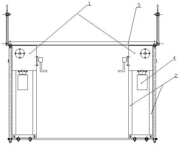
[0015] The motor 4 is fixedly connected to the gear box 1, the gear box 1 is fixedly connected to the gear box bracket 2, and the gear box bracket 2 is fixedly connected to the bottom plate and the guardrail bracket 3 through bolts;

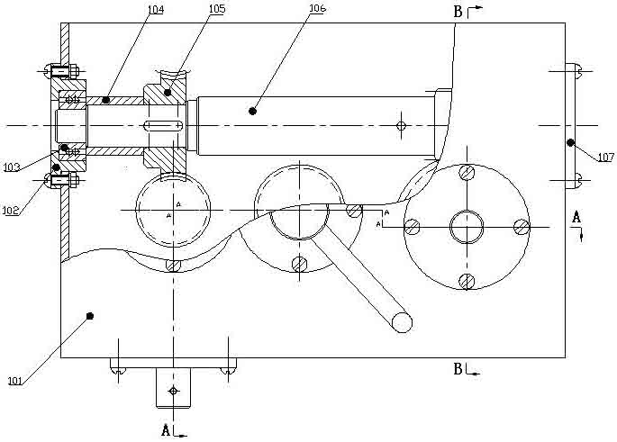
[0016] The structure of the gearbox 1 is that the shaft sleeve I104 and the worm gear I105 are installed on the winding worm shaft 106, the ball bearing I103 and the ball bearing IX136 are respectively set on the two ends of the winding worm shaft 106, the ball bearing I103 is embedded on the bearing sleeve I102, the ball Bearing Ⅸ136 is embedded on bearing sleeve Ⅱ107, shaft sleeve Ⅳ129 and worm wheel Ⅱ130 are installed on shaft 131, ball bearing Ⅶ128 and ball bearing Ⅷ133 are respectively set on both ends of shaft 131, ball bearing Ⅶ128 is embedded on bearing sleeve Ⅷ127, ball bearing Ⅷ133 is embedded On the bearing sleeve IX132, the shaft sleeve V134 and the cylindrical gear II135 are installed on the manual input shaft 126, the ball bearing II...


PUM


Abstract

The invention relates to a controllable high-rise escaper belonging to a high-rise lifesaving appliance. A motor is fixedly connected with a gear box, the gear box is fixedly connected with a gear box bracket, and the gear box bracket is fixedly connected with a guardrail bracket through bolts and a bottom plate. The invention has the advantages of novel, simple and compact structure, conveniencefor machining and manufacturing, low cost, easiness in operation and strong practical applicability.

Description

technical field [0001] The invention belongs to high-rise lifesaving equipment. Background technique [0002] With the gradual increase of high-rise buildings in China, more and more high-altitude rescue and high-altitude construction facilities are needed. In case of fire and emergency, simple escape tools composed of pulleys and ropes are often used, while the existing large-scale high-rise escape devices are safe. Poor performance, difficult operation, cumbersome, not easy to rescue people trapped in high buildings in a safe and timely manner. Contents of the invention [0003] The invention provides a controllable high-rise escape device to solve the problems of poor safety and difficult operation of existing equipment. [0004] The technical scheme adopted by the present invention is: the motor is fixedly connected with the gear box, the gear box is fixedly connected with the gear box bracket, and the gear box bracket is fixedly connected with the bottom plate and th...

Claims


Application Information

Patent Timeline
Patent Type & Authority Applications(China)
IPC IPC(8): A62B1/06
Inventor 姜大伟王占礼张邦成庞在祥朱立峰李学光田园赵云谢涵高智陈立岩柳虹亮蔡赟费树名姚禹
Owner CHANGCHUN UNIV OF TECH
Why Eureka
Try Eureka