Wave guide direction control method based on sweep frequency multi-channel electromagnetic ultrasonic wave guide device

An ultrasonic guided wave and direction control technology, which is applied in the generation of ultrasonic/sonic/infrasonic waves, analysis materials, instruments, etc., can solve the problems of inability to control the direction of guided waves, remote online monitoring, etc.

Active Publication Date: 2017-09-01
HARBIN INST OF TECH
View PDF2 Cites 4 Cited by
  • Summary
  • Abstract
  • Description
  • Claims
  • Application Information

AI Technical Summary

Problems solved by technology

[0004] In order to solve the problem that the existing guided wave direction control method cannot use a multi-channel electromagnetic ultrasonic guided wave transducer to excite and receive unidirectionally

Method used


Image

  • Wave guide direction control method based on sweep frequency multi-channel electromagnetic ultrasonic wave guide device
  • Wave guide direction control method based on sweep frequency multi-channel electromagnetic ultrasonic wave guide device
  • Wave guide direction control method based on sweep frequency multi-channel electromagnetic ultrasonic wave guide device

Examples


specific Embodiment approach 1

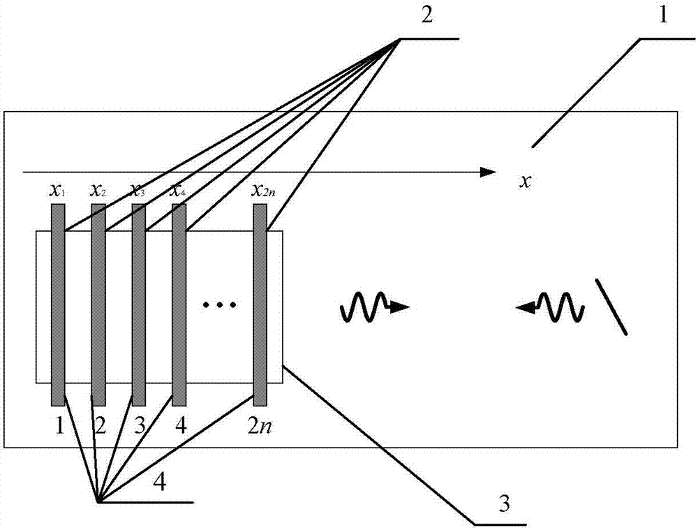
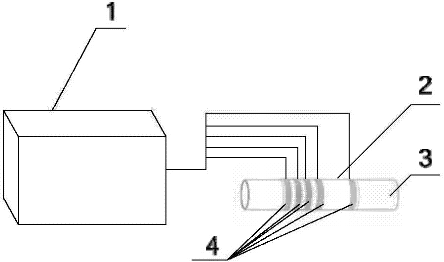
[0020] Specific implementation mode 1: a method for controlling the guiding direction of a wave based on a frequency-sweeping multi-channel electromagnetic ultrasonic wave guiding device, such as figure 1 As shown, the frequency-sweeping multi-channel ultrasonic guided wave device includes a multi-channel ultrasonic guided wave transmitting and receiving device 1, an iron-cobalt alloy strip 2, a test piece 3 and a transmitting coil array 4, and the iron-cobalt alloy strip 2 is tightened by applying pressure or bonding. Attached to the surface of the test piece 3, the transmitting coil array 4 is located on the surface of the iron-cobalt alloy strip 2, one end of each transmitting coil in the transmitting coil array 4 is connected to one transmitting channel of the multi-channel ultrasonic guided wave transmitting and receiving device 1, and the other is grounded, and the iron The cobalt alloy strip 2 and the transmitting coil array 4 form a transducer. In order to excite ultras...

specific Embodiment approach 2

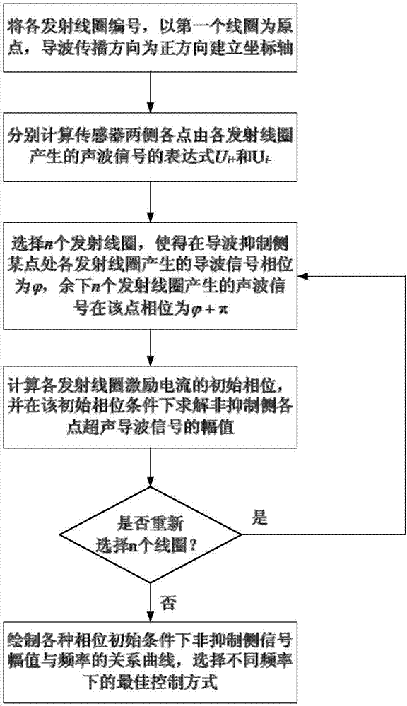
[0028] Specific embodiment two: the difference between this embodiment and specific embodiment one is: the coordinate axis described in step two is the transmitting coil T 1 is the origin, and the direction of guided wave propagation is the positive direction, and the corresponding coordinates of each transmitting coil are x 1 , x 2 ,...,x 2n , where x 1 =0,x i is the distance from the i-th coil to the first coil, i=1, 2, 3, . . . , 2n. ; Other steps and parameters are the same as in the first embodiment.

specific Embodiment approach 3

[0029] Specific embodiment three: the difference between this embodiment and specific embodiment one or two is: in step three, the initial phase steps of calculating the excitation current of each coil are as follows:

[0030] (1) Solve the characteristic equation of the guided wave in the tested piece by numerical solution or special software according to the parameters of the tested piece, and obtain the wave velocity c of the guided wave;

[0031] (2), the excitation current signal of each transmitting coil is Wherein i=1, 2,..., 2n, wherein f is the frequency of the guided wave, I is the excitation current amplitude, and t is the guided wave propagation time, is the initial phase;

[0032] (3), for any position x>0, at t 0 time at which the coil T is transmitted i The resulting guided wave signal is U(x) is the amplitude when the ultrasonic guided wave propagates to x;

[0033] For any position x0 time at which the coil T is transmitted i The resulting guided wave...


PUM


Abstract

The invention discloses a wave guide direction control method based on a sweep frequency multi-channel electromagnetic ultrasonic wave guide device, relates to a wave guide direction control method, and aims to solve the problem that a multi-channel electromagnetic ultrasonic wave guide transducer cannot excite or receive single-way transmission ultrasonic guide waves of any frequency by using a conventional wave guide direction control method under the condition that a coil wiring mode is not changed. The method comprises the following steps: firstly, calculating initial phase of excitation current of different coils, and adjusting the initial phase of the excitation current of the coils till the vibration amplitude of one side of which wave guide signals are suppressed is zero after signals are overlapped; calculating the vibration amplitude of a non-suppressed side after wave guide signals generated from the emitting coils are synthesized; drawing a relationship curve of the vibration amplitude and the frequency of wave guide signals of the non-suppressed side, and at different working frequencies, selecting corresponding initial phase of excitation current when the vibration amplitude of the wave guide signals is maximum; finally selecting a suppressed side or a non-suppressed side, thereby achieving direction control. The wave guide direction control method is applied to nondestructive detection on metal plates, tubes and the like.

Description

technical field [0001] The invention belongs to the technical field of non-destructive testing, and in particular relates to a method for controlling the direction of guided waves, which is used for non-destructive testing of metal plates, pipe fittings and the like. Background technique [0002] With the continuous development of my country's industrialization level, it is of great significance to regularly inspect and monitor the health of industrial structures to ensure their safe operation. Therefore, the application of non-destructive testing technology is becoming more and more extensive, especially the ultrasonic guided wave testing technology, which has the technical advantages of high detection efficiency and low cost, and is suitable for defect detection and health monitoring of large industrial structures. [0003] The electromagnetic ultrasonic guided wave detection method is easier to control the type, mode and propagation direction of the guided wave by changin...

Claims


Application Information

Patent Timeline
IPC IPC(8): G01N29/34
CPCG01N29/34G01N2291/023G01N2291/0289
Inventor 王淑娟李策贾文斌赵普翟国富
Owner HARBIN INST OF TECH
Why Eureka
Try Eureka