Electrolyte directional controllable electrolytic milling machining device and machining process thereof

A technology of milling processing and electrolyte, which is applied in the direction of electric processing equipment, electrochemical processing equipment, and the supply of processing working media. problem, to achieve the effect of improving stability

Active Publication Date: 2021-08-06
GUANGDONG UNIV OF TECH
View PDF6 Cites 5 Cited by
  • Summary
  • Abstract
  • Description
  • Claims
  • Application Information

AI Technical Summary

Problems solved by technology

However, in this solution, only hole-like parts can be processed. When electrolytic milling is performed, the electrolyte cannot be obtained in the gap in the processing direction, so that the surface of the workpiece cannot be electrolytically milled, and the electrolytic machining of large depth-of-cut structures cannot be realized, and high-pressure gas will hinder electrolysis. The liquid discharges the electrolytic product, which affects the stability of the processing process and the surface quality

Method used


Image

  • Electrolyte directional controllable electrolytic milling machining device and machining process thereof

Examples


Embodiment 1

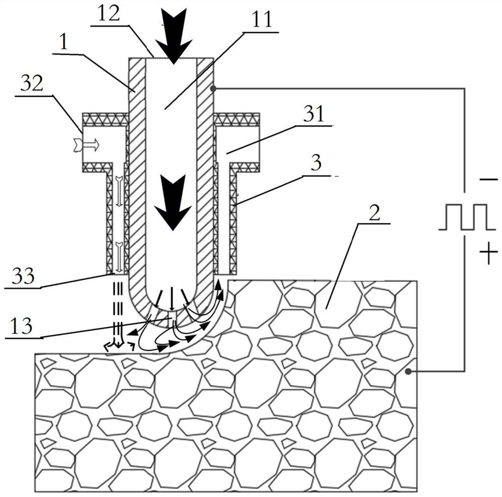
[0030] Such as figure 1 As shown, an electrolytic milling device with controllable electrolyte orientation includes a power supply and a tubular tool electrode 1, the negative pole of the power supply is connected to the tool electrode 1, the positive pole of the power supply is connected to the workpiece 2, and a power supply is provided inside the tool electrode 1. The liquid chamber 11 where the liquid solution flows, the two ends of the tool electrode 1 are respectively provided with a liquid inlet 12 and a liquid outlet 13 communicating with the liquid chamber 11, a number of nozzles 3 are fixed in a fixed array around the tool electrode 1, and the nozzles 3 are provided with high pressure The gas chamber 31 for gas circulation, the two ends of several nozzles 3 are respectively provided with air inlets 32 and air outlet holes 33 communicating with the gas chamber 31, and several air outlet holes 33 are fixedly arrayed around the liquid outlet hole 13, and the liquid outle...

Embodiment 2

[0040] This embodiment is the processing technology of the above-mentioned electrolytic milling processing device with controllable electrolyte orientation, including the following steps:

[0041] S1: fix the nozzle 3 array around the tool electrode 1;

[0042] S2: Connect the tool electrode 1 to the negative pole of the power supply, and the workpiece 2 to be processed to the positive pole of the power supply;

[0043] S3: Pass the electrolyte from the liquid inlet 12 to the liquid chamber 11 inside the tool electrode 1, and the electrolyte is sprayed out through the liquid outlet 13; selectively open a number of nozzles 3, and pass into a number of nozzles 3 from the air inlet 32 High-pressure gas, the high-pressure gas is ejected from several air outlet holes 33;

[0044] S4: Turn on the power, control the tool electrode 1 to move along the machining path, and realize the electrolytic milling process with controllable orientation of the electrolyte.

[0045] In the electr...


PUM


Abstract

The invention relates to the technical field of electrolytic machining, in particular to an electrolyte directional controllable electrolytic milling machining device and a machining process thereof. The device comprises a power source and a tubular tool electrode. The negative electrode and the positive electrode of the power source are connected with the tool electrode and a workpiece correspondingly, a liquid cavity allowing an electrolyte to flow is formed in the inner side of the tool electrode, a liquid inlet and a liquid outlet hole which communicate with the liquid cavity are arranged at the two ends of the tool electrode correspondingly, multiple nozzles capable of being selectively opened or closed are fixedly arrayed on the periphery of the tool electrode, the nozzles are provided with gas outlet holes capable of spraying out high-pressure gas, the multiple gas outlet holes are fixedly arrayed on the periphery of the liquid outlet hole, and the liquid outlet hole can spray out the electrolyte to machine the workpiece. According to the device and the process, the flow direction of the electrolyte can be directionally controlled, so that the sufficient electrolyte is obtained in a gap of a machining area, an electrolytic product is discharged, electrolytic machining of any molded surface structure such as a large-cutting-depth structure is realized, and the stability of the electrolytic milling machining process and the surface quality of the machined workpiece are improved.

Description

technical field [0001] The invention relates to the technical field of electrolytic machining, and more specifically, to an electrolytic milling device and a machining process with controllable electrolyte orientation. Background technique [0002] Electrolytic machining is a manufacturing technology that uses the principle of electrochemical dissolution of metal anodes to remove materials. It has many unique advantages, such as no tool loss, independent of material hardness, high productivity, good surface quality, and three-dimensional complex shapes can be processed. Electrolytic machining has become a key technology in the aerospace manufacturing industry and is widely used in the production of engine blades and other parts. Electrolytic machining has been used in many industries such as weapons, automobiles, medical equipment, electronics, and molds. However, in the process of electrolytic machining, the flow field of the electrolyte in the machining gap has a direct r...

Claims


Application Information

Patent Timeline
Patent Type & Authority Applications(China)
IPC IPC(8): B23H3/00B23H3/10B23H11/00
CPCB23H3/00B23H3/10B23H11/00
Inventor 张传运蒋庆财陈晓磊张永俊
Owner GUANGDONG UNIV OF TECH
Why Eureka
Try Eureka