Continuous milling machine and traveling and loading control system

A control system and technology of continuous miner, which are applied in the directions of driving device, earthwork drilling, slitting machinery, etc., can solve the problems such as the inability to increase the speed of hydraulic motor in real time, the inability to realize the improvement of speed, and the influence of the working efficiency of the continuous miner, etc. Achieve the effect of realizing self-adaptive control, improving walking efficiency, and increasing loading torque

Inactive Publication Date: 2013-07-17
SANY HEAVY EQUIP
View PDF8 Cites 5 Cited by
  • Summary
  • Abstract
  • Description
  • Claims
  • Application Information

AI Technical Summary

Problems solved by technology

Therefore, when the continuous miner is running in the empty roadway, if the continuous miner is in the state of no-load travel, its travel speed is limited by the hydraulic control system, and the speed of the hydraulic motor cannot be increased in real time. Therefore, the travel efficiency is low (due to the hydraulic pressure The pump control has only one speed, whether it is empty or full load, the speed cannot be increased, if the frequency conversion motor is used to work, the speed can be adjusted in real time); at the same time, when loading coal and rocks with different weights, the star wheel in the loading part The loading speed cannot be changed, and the loading efficiency is low
[0003] In addition, the loading part and walking part of the continuous miner also have the problem of cooperative operation, (such as when the continuous miner is cutting coal, the shovel part is in the loading state, and the continuous miner moves forward at this time, which will inevitably cause the shovel Accumulation of coal and rocks in the inner part makes the star wheel overloaded) which also affects the working efficiency of the continuous miner

Method used


Image

  • Continuous milling machine and traveling and loading control system
  • Continuous milling machine and traveling and loading control system

Examples


Embodiment Construction

[0028] It should be noted that, in the case of no conflict, the embodiments of the present invention and the features in the embodiments can be combined with each other. The present invention will be described in detail below with reference to the accompanying drawings and examples.

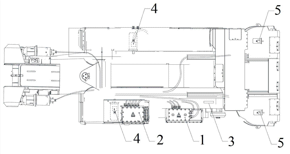
[0029] Combine below Figure 1 to Figure 2 , the embodiment of the traveling and loading control system of the preferred embodiment of the present invention will be further described in detail.

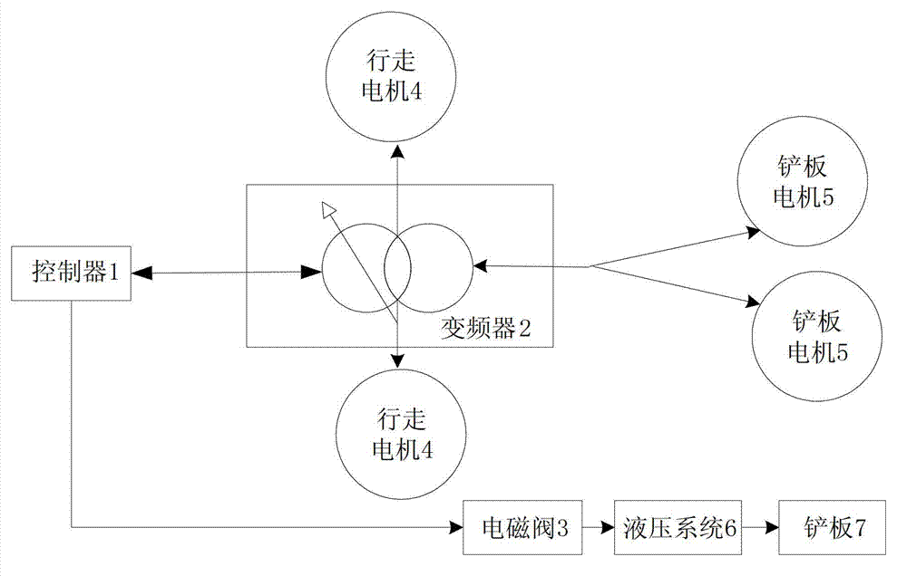
[0030] refer to figure 1 , the travel and loading control system of this embodiment is used for continuous mining machines, including: a controller, at least two frequency converters, a travel motor, and a scraper motor; the controller 1 is connected to the inverter 2; the travel motor 4 and the scraper motor The motors 5 are also connected to the frequency converter 2 respectively; wherein, the frequency converter 2 is used to detect the operating current of the travel motor 4 and / or the shovel motor ...


PUM


Abstract

The invention discloses a continuous milling machine and a traveling and loading control system. The traveling and loading control system comprises a controller, at least two paths of frequency converters, a traveling motor and a shovel motor, wherein the controller is connected with the frequency converter; the traveling motor and the shovel motor are respectively connected with the frequency converters; the frequency converters are used for detecting the working current of the traveling motor and/or the shovel motor; the controller receives the working current and controls the output signals of the frequency converters according to the magnitude of the working current; and the output signals are used for changing the rotating speed of the traveling motor and/or the shovel motor. According to the continuous milling machine and the traveling and loading control system, the frequency converters are connected with the traveling motor, so that the traveling speed can be changed in real time, and the traveling efficiency is improved; and besides, the frequency converters are connected with the shovel motor, so that the loading capacity of a star wheel of the shovel part is enhanced, and the loading efficiency is improved.

Description

technical field [0001] The invention relates to the field of engineering machinery, in particular to a continuous mining machine and a traveling and loading control system. Background technique [0002] At present, the traveling part and loading part of the continuous miner are controlled by hydraulic control system. Therefore, when the continuous miner is running in the empty roadway, if the continuous miner is in the state of no-load travel, its travel speed is limited by the hydraulic control system, and the speed of the hydraulic motor cannot be increased in real time. Therefore, the travel efficiency is low (due to the hydraulic pressure The pump control has only one speed, whether it is empty or full load, the speed cannot be increased, if the frequency conversion motor is used to work, the speed can be adjusted in real time); at the same time, when loading coal and rocks with different weights, the star wheel in the loading part The loading speed cannot be changed, a...

Claims


Application Information

Patent Timeline
Patent Type & Authority Applications(China)
IPC IPC(8): E21C31/02E21C35/24
Inventor 易定忠赵继伟刘兴利
Owner SANY HEAVY EQUIP
Why Eureka
Try Eureka