Sauna apparatus

一种桑拿、空气的技术,应用在洗浴装置、物理治疗等方向,能够解决通气抵抗增大、结构复杂等问题

Inactive Publication Date: 2009-03-04
PANASONIC CORP
View PDF1 Cites 13 Cited by
  • Summary
  • Abstract
  • Description
  • Claims
  • Application Information

AI Technical Summary

Problems solved by technology

However, if this structure is adopted, the ventilation resistance will increase
or the structure becomes complex

Method used


Image

  • Sauna apparatus
  • Sauna apparatus
  • Sauna apparatus

Examples


Embodiment Construction

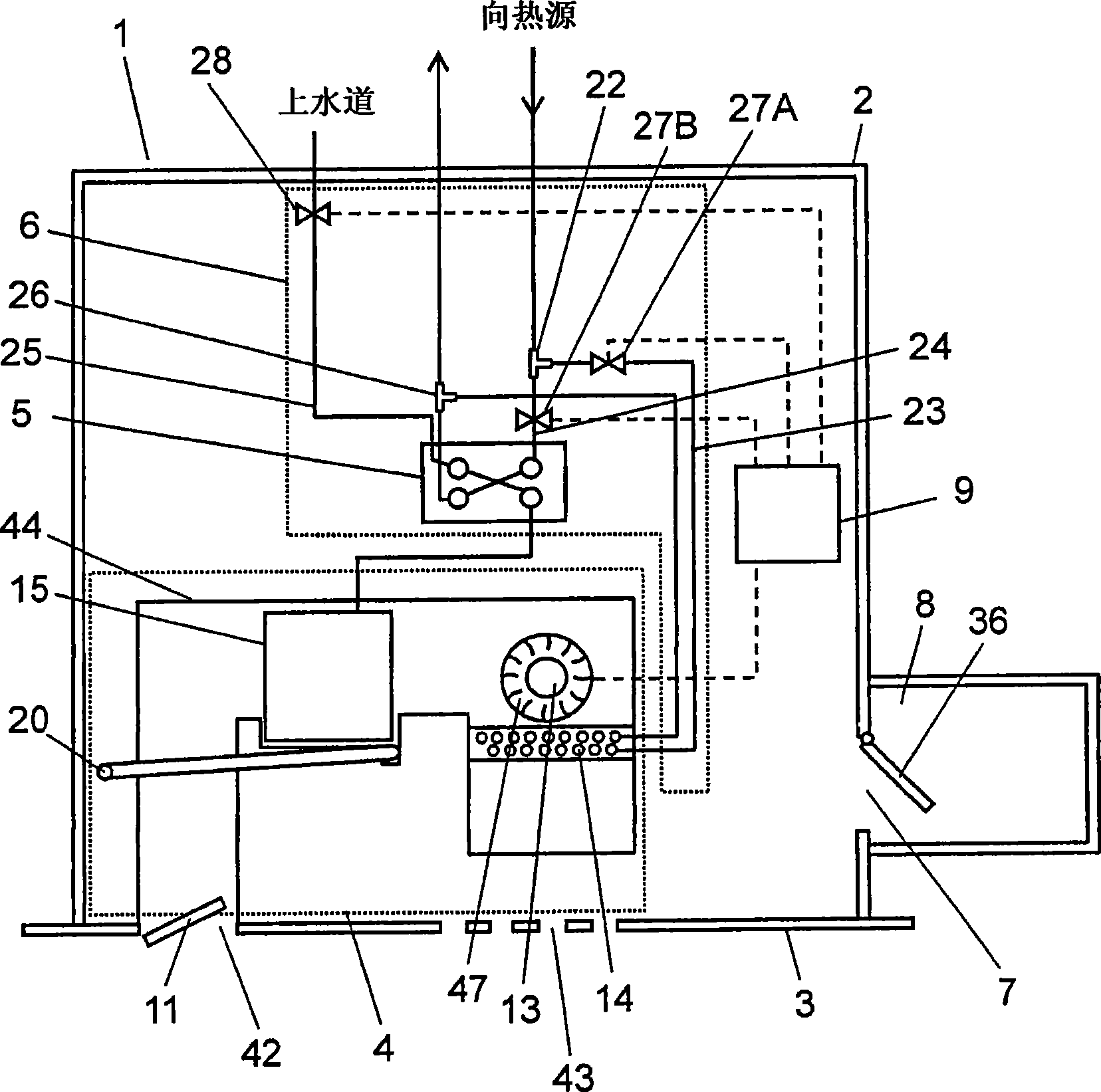
[0080] figure 1It is a schematic configuration diagram showing the sauna device according to the embodiment of the present invention. The sauna device 1 has an exterior body 2 , a front panel 3 , a sauna module 4 , a heat supply unit 6 , a ventilation unit 8 , and a control unit 9 . The exterior body 2 forms the outer contour of the sauna device 1 . The front panel 3 forms one surface of the exterior body 2 on the bathroom side. The sauna module 4 sucks the air in the bathroom, blows it into the bathroom again after it is heated and humidified. The heat supply unit 6 includes a plate heat exchanger 5 . The ventilation unit 8 is provided on one surface of the exterior body 2, and is connected to the opening 7 communicating with the air supply path. The control unit 9 controls them. Next, their specific structures will be described.

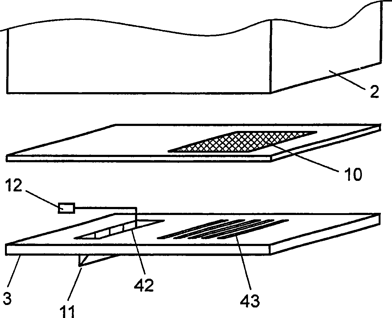
[0081] figure 2 It is an exploded schematic diagram when the front panel 3 is removed. The front panel 3 is provided with an inlet 43 fo...


PUM


Abstract

A sauna apparatus that even when spraying into blast channel for humidification is carried out, realizes formation of relatively minute water droplets and increasing of the rate of humidification, and that by relatively simple architecture, avoids outblowing of water droplets of large diameter into bathroom. There is provided an apparatus including humidifying section (15) equipped with blowing unit (47) for air suctioning and blasting; a blast channel adapted to deliver not only suctioned air but also humidified air; spraying unit (45) structured so as to spray a humidification water to the air passing through the blast channel, thereby attaining humidification of the air; and sprayed water droplet atomizing unit (16) disposed in the direction of humidification water spraying by the spraying unit so as to realize collision of the sprayed water droplets, thereby attaining atomization of the water droplets.

Description

technical field [0001] The present invention relates to a sauna (sauna) device that turns a room such as a bathroom into a sauna space by heating and humidifying the room. Background technique [0002] Figure 10 It is a schematic diagram of the structure of the conventional sauna apparatus. Such a sauna device is disclosed in Patent Document 1, for example. Next, a conventional sauna device will be described. [0003] In this sauna device, an air outlet 102 and an air inlet 103 opening into the bathroom 101 are provided. The suction port 103 communicates with the blower port 102 through the air supply path 104 . A spray nozzle (hereinafter referred to as a nozzle) 105 is provided in the air supply passage 104 . The nozzle 105 is connected to a water supply heater 106 . A cross-flow fan 107 is provided in the suction port 103 . [0004] The warm air generator 108 provided in the air supply path 104 has a casing 109 . The casing 109 is provided with an air intake commu...

Claims


Application Information

Patent Timeline
Patent Type & Authority Applications(China)
IPC IPC(8): A61H33/06
CPCA61H33/065A61H33/063
Inventor 斋藤和大西水流芳宽
Owner PANASONIC CORP
Why Eureka
Try Eureka