
Input apparatus

A technology of input device and input operation, which is applied in the direction of measurement device, input/output process of data processing, instruments, etc., can solve problems such as complicated operation, and achieve the effect of simple input operation

Active Publication Date: 2009-03-18
ALPS ALPINE CO LTD
View PDF1 Cites 21 Cited by
  • Summary
  • Abstract
  • Description
  • Claims
  • Application Information

AI Technical Summary

Problems solved by technology

[0004] However, in the above-mentioned patent document 1, a certain one of the above-mentioned switch parts is used as a decision button (confirmation button), for example, and is input by an operating body in a flat type input device. After moving the information, since the decision button is pressed, once the finger is released from the operation surface, the finger must be moved to the position of the decision button, and there is a problem that the operation is complicated.

Method used


Image

  • Input apparatus
  • Input apparatus
  • Input apparatus

Examples


Embodiment Construction

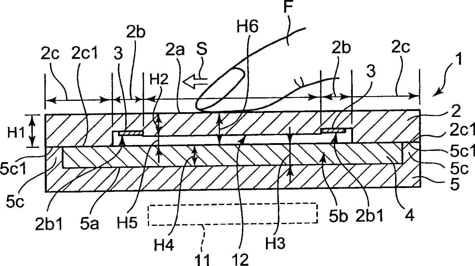
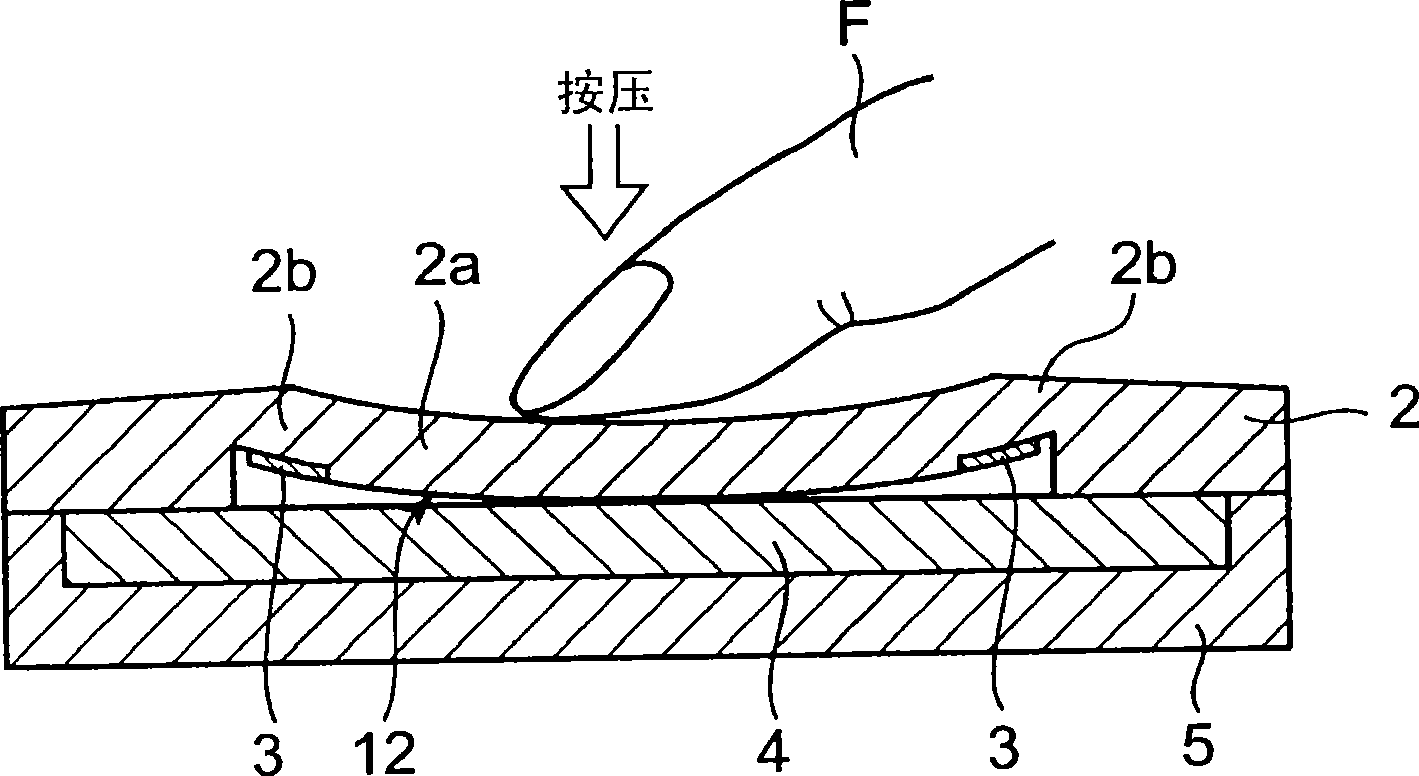
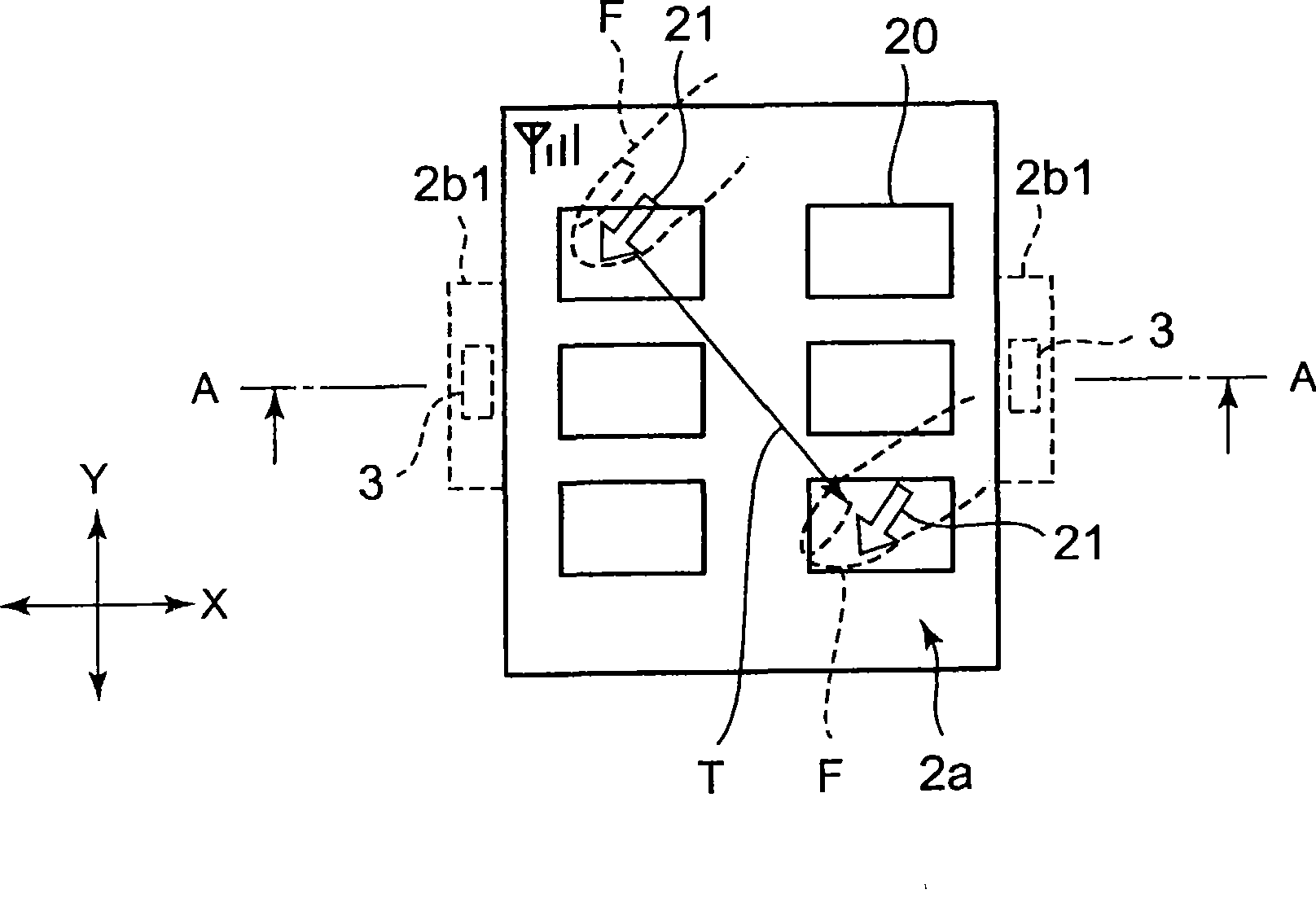
[0023] figure 1 It is a cross-sectional view of the input device according to the first embodiment of the present invention (cut along line A-A in the direction of thickness dimension) image 3 The input device shown, observe the cross-sectional view of its cut surface from the direction of the arrow), figure 2 means to press with finger F on the figure 1 A cross-sectional view of the above-mentioned input device in the state shown on the operating area of ​​the input device, image 3 is a partial plan view of the input device in this embodiment, Figure 4 This is a diagram of the circuit configuration for detecting the amount of pressing (deflection), Figure 5 It is a graph (analog signal output waveform diagram) showing the relationship between the pressing amount (deflection amount) and output, Image 6 is a cross-sectional view of an input device according to a second embodiment of the present invention, Figure 7 is built in Image 6 Top view of the capacitive sen...


PUM


Abstract

The invention provides an input apparatus which can perform simple input operation compared with prior apparatus. The input apparatus includes a surface plate 2, an electrostatic capacitive sensor 4 disposed under the surface plate 2, and a strain sensor 3 disposed between the electrostatic capacitive sensor 4 and the surface plate 2 and fixed to the back surface of the surface plate 2. As a first input operation, when a finger F is moved on an operation area 2a of the surface plate 2, the movement position can be detected by the electrostatic capacitive sensor 4. As a second input operation, when the operation area 2a is pressed down, the pressing force can be detected by the strain sensor 3. A series of the first input operation and the second input operation can be performed without leaving the finger F from the operation area 2a. Therefore, the input operation can be simply performed.

Description

technical field [0001] The present invention relates to an input device that enables simpler input operations than conventional ones. Background technique [0002] In the invention described in Patent Document 1 below, there are provided a planar input device capable of coordinate input, and switch units corresponding to push buttons on the lower side of the planar input device. [0003] Patent Document 1: Japanese Patent Laid-Open No. 2002-123363. [0004] However, in the above-mentioned Patent Document 1, one of the above-mentioned switch parts is used as a decision button (confirmation button), for example. After the movement information is input by the operating body in the flat-type input device, since the above-mentioned decision button is pressed, once the finger moves from the operation There is a problem that it is necessary to move the finger to the position of the above-mentioned determination button if the user faces away, and the operation is complicated. Con...

Claims


Application Information

Patent Timeline
Patent Type & Authority Applications(China)
IPC IPC(8): G06F3/041G06F3/044
CPCG01L1/20G06F3/0414G06F3/044
Inventor 佐藤忠满
Owner ALPS ALPINE CO LTD
Learn More