
Elastic rewinding hose reel with automatic stopping device
A brake mechanism, hose technology, applied in the direction of thin material handling, transportation and packaging, etc., can solve problems such as wear, drum acceleration, and difficulty for the operator to manually stop the hose
- Summary
- Abstract
- Description
- Claims
- Application Information
AI Technical Summary
Problems solved by technology
Method used
Image

Examples
Embodiment Construction
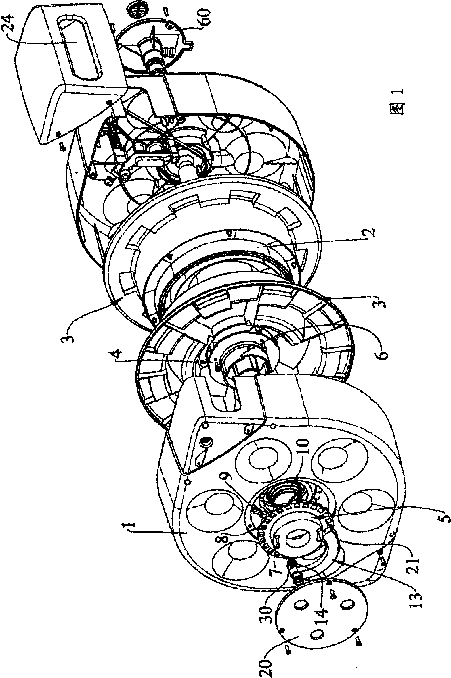
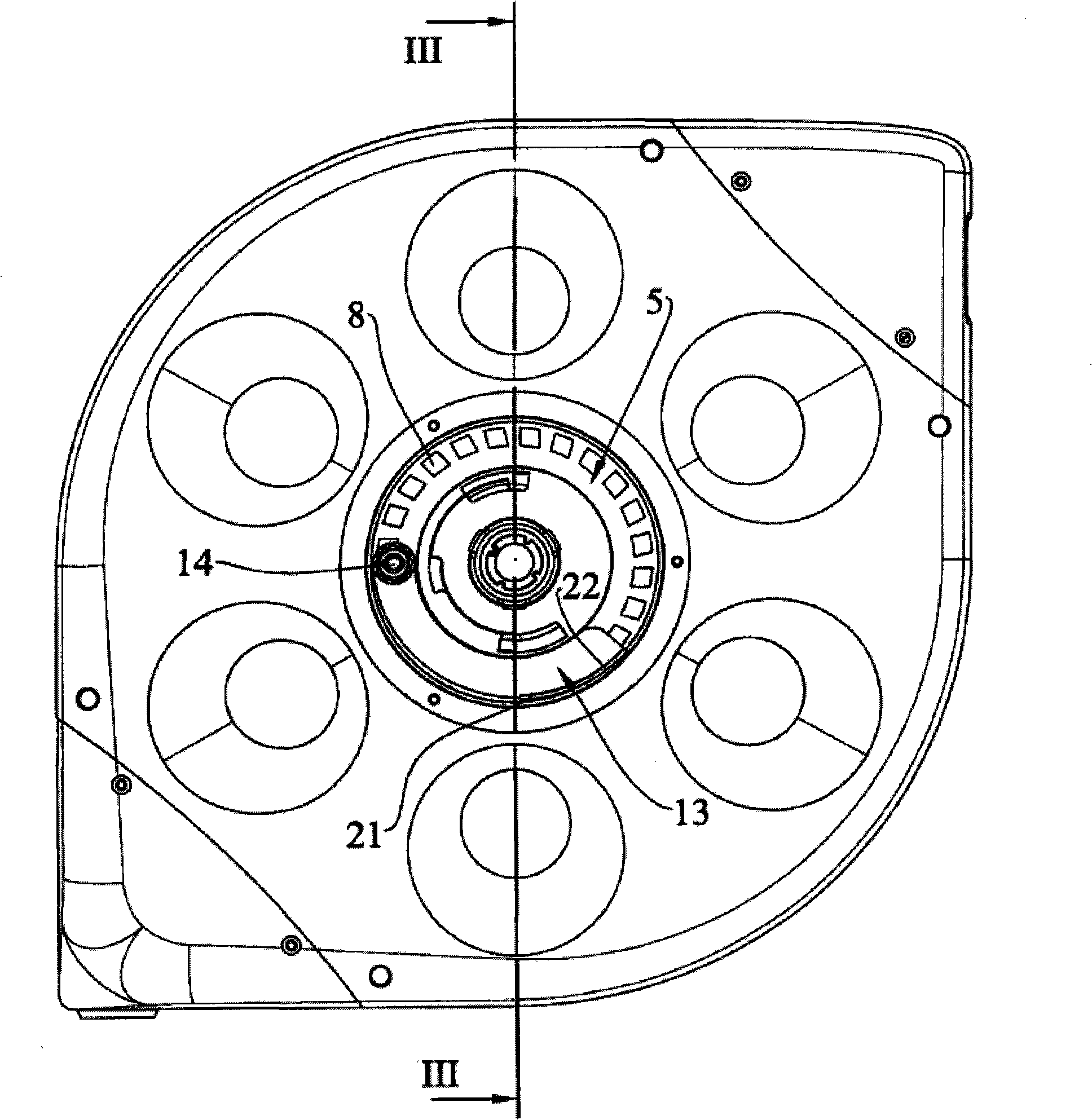
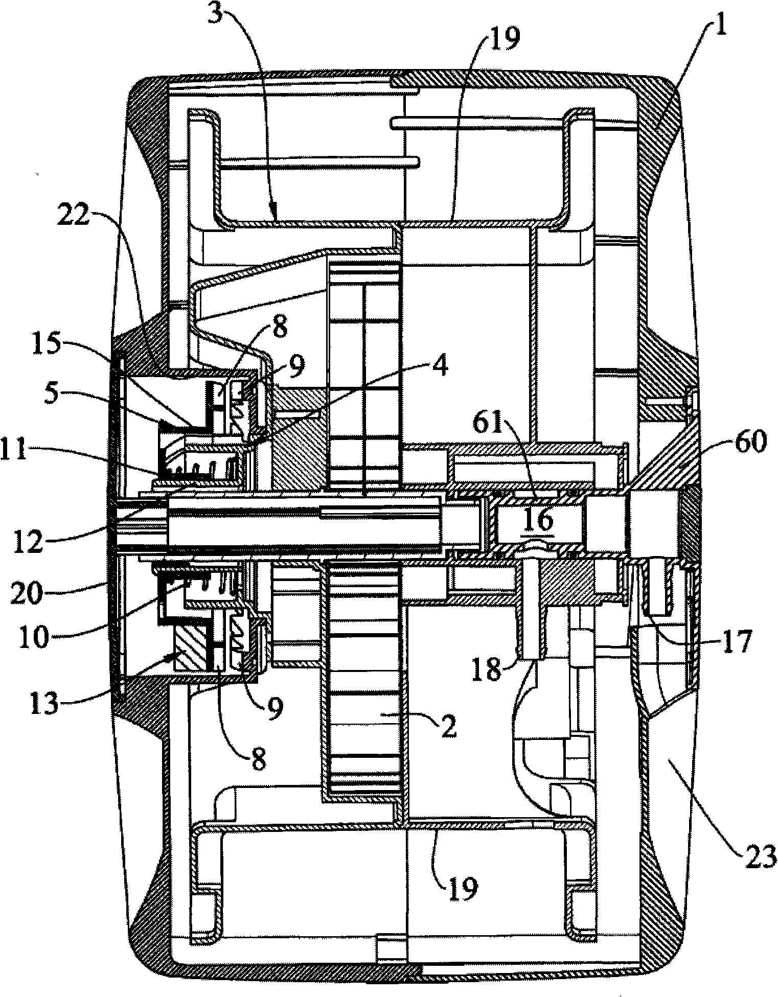
[0031] The hose reel shown in the accompanying drawings comprises a housing 1 which rotatably supports a drum 3 which is pressed in an angular rest position by a rewind spring 2 and has a rotatable axial It is connected to the flange 4 of the locking disc 5 which also has teeth 8 which can engage with corresponding teeth 9 on the housing 1 .
[0032] Said flange 4 comprises a raised surface portion 51 which is engageable with a corresponding protrusion 52 of the locking disc 5 during the unwinding and rewinding phases of the hose, said flange 4 also comprises a cam 6 which Engage with the corresponding cam 7 on the lock disc 5 (Fig. 8-12). The lock disc 5 has an inner sleeve 11, which is rotatably and axially installed on the cylindrical connecting portion 12 of the flange 4, and a pre-compressed separation spring 10 is provided between the lock disc 5 and the flange 4 for The locking disc 5 is kept axially spaced from the flange 4, thereby keeping the teeth 8 of the locking ...
PUM
 Abstract
Description
Claims
Application Information