Fuel box connector mounting structure

A technology for installing structures and connectors, which is applied in the installation, connection, substructure and other directions of connecting components, which can solve the problems of increasing the number of parts and increasing the number of connector processing procedures.

Inactive Publication Date: 2004-03-17
KEIHIN CORP
View PDF0 Cites 0 Cited by
  • Summary
  • Abstract
  • Description
  • Claims
  • Application Information

AI Technical Summary

Problems solved by technology

[0016] In addition, in Figure 10 In the example shown, since the elastic engaging member 62 must be made of a long and thin metal pin and must be integrated with the connector, the number of parts and the number of connector processing steps increase
Therefore, this structure is not the best

Method used


Image

  • Fuel box connector mounting structure
  • Fuel box connector mounting structure
  • Fuel box connector mounting structure

Examples


Embodiment Construction

[0043] A detailed description of an embodiment of the fuel tank connector mounting structure according to the present invention will be given below with reference to the accompanying drawings.

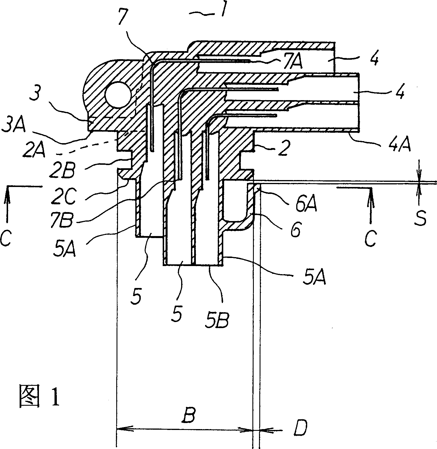
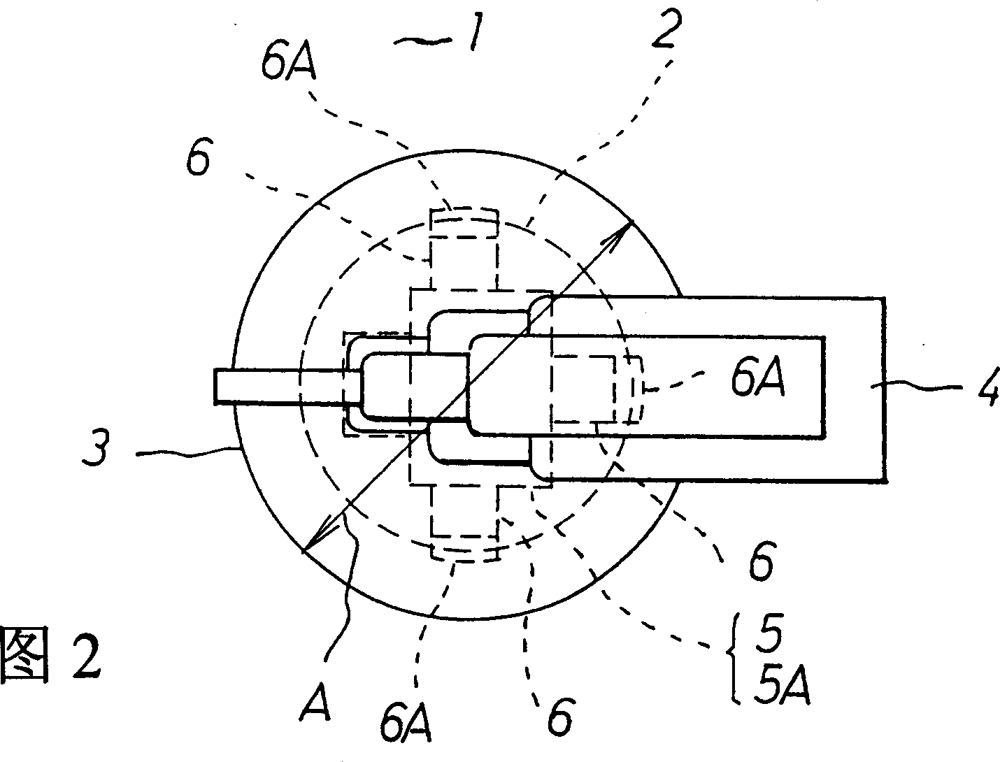
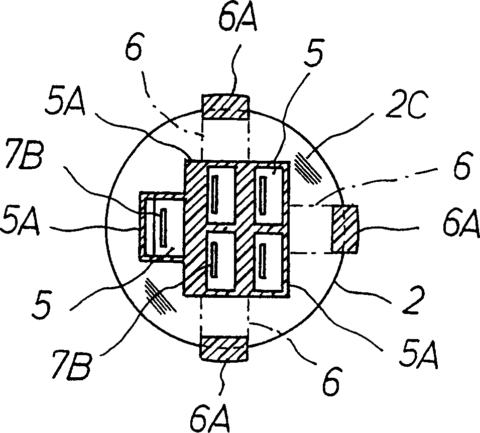
[0044] Figure 1 is a vertical sectional view of the fuel tank connector, Figure 2 is a top view of the upper part of Figure 1, and image 3 It is a horizontal cross-sectional view along line C-C in Fig. 1.

[0045] Reference numeral 1 denotes a fuel tank connector, which is composed of the following components.

[0046] Reference numeral 2 denotes a tubular portion in the form of a circle, and a flange portion 3 having a diameter A larger than a diameter B of the tubular portion 2 is formed on an upper end surface 2A of the tubular portion 2 .

[0047] In addition, an annular sealing groove 2B is formed on the outer surface of the tubular portion 2 .

[0048]In addition, an external power supply side terminal plug receiving groove portion 4 is formed above the upper end surface 2A of...


PUM


Abstract

A mounting structure of a connector for a fuel tank is made suitable for a two-wheeled vehicle by making small a downward protrusion of a fuel tank side terminal pin receiving recess portion from the lower surface of the lid body with the constitution such that the connector (1) is provided with a tubular portion (2) in a cylindrical shape, the fuel tank side terminal pin receiving recess portion (5) protruding downward from the tubular portion (2), and an engagement piece portion (6) formed in an outer peripheral portion of the fuel tank side terminal pin receiving recess portion (5) and having an engagement portion (6A), an insertion hole portion (11) with a fuel tank side terminal pin receiving recess portion insertion hole (11A) and an engagement piece insertion hole (11B) being provided connectively is provided in a lid body (10), a sleeve (12) is fixedly arranged on the upper surface (10A) of the lid body (10), the tubular portion (2) is supported to the sleeve (12) via a seal ring (R), the lower surface (3A) of a flange portion (3) is brought into contact with the upper end (12B) of the sleeve (12), and the engagement portion (6A) is brought into contact with the lower end (12B) of the sleeve (12) via the engagement piece insertion hole (11B).

Description

technical field [0001] The invention relates to an installation structure of a fuel tank connector. The connector is installed on the wall of the fuel tank of vehicles such as automobiles and motorcycles and connects electrical equipment installed in the fuel tank with an external power supply outside the fuel tank. Background technique [0002] FIG. 9 shows a first example of a conventional mounting structure of a connector of an oil tank (hereinafter referred to as a connector). [0003] The sleeve 51 is adhered to the cover plate 50 fixed on the wall of the fuel tank by brazing. Surface 50B extends downwardly from the lower end of sleeve 51 and has tongue 51B near the lower end. The connector 52 is formed in an L shape, and one end of the connector 52 is formed with an outer connecting portion 53 protruding to the right, and at the other end of the connector 52 is formed an inner connecting portion 54 protruding downward. Ends of a plug-in terminal pin 55 inserted in th...

Claims


Application Information

Patent Timeline
IPC IPC(8): B60K15/03F02M37/10H01R13/42H01R13/46H01R13/73H01R13/74H01R31/06
CPCY02T10/123Y02T10/12
Inventor 大沼伦郎
Owner KEIHIN CORP
Why Eureka
Try Eureka