Whirl-stop device for rocker arm shaft in valve mechanism of internal combustion engine

A technology for internal combustion engines and rocker shafts, applied in the field of anti-rotation devices, which can solve problems such as labor-intensive assembly, difficult space design, and increased rocker shafts

Inactive Publication Date: 2010-01-13
HONDA MOTOR CO LTD
View PDF5 Cites 0 Cited by
  • Summary
  • Abstract
  • Description
  • Claims
  • Application Information

AI Technical Summary

Problems solved by technology

[0008] The above countermeasure ① not only increases the number of parts and costs, but also makes the design difficult because it takes up too much space
In addition, the above counterme

Method used


Image

  • Whirl-stop device for rocker arm shaft in valve mechanism of internal combustion engine
  • Whirl-stop device for rocker arm shaft in valve mechanism of internal combustion engine
  • Whirl-stop device for rocker arm shaft in valve mechanism of internal combustion engine

Examples


Embodiment Construction

[0017] Hereinafter, embodiments of the present invention will be described based on examples of the present invention shown in the drawings.

[0018] First, refer to Figure 1~4 An embodiment of the present invention will be described.

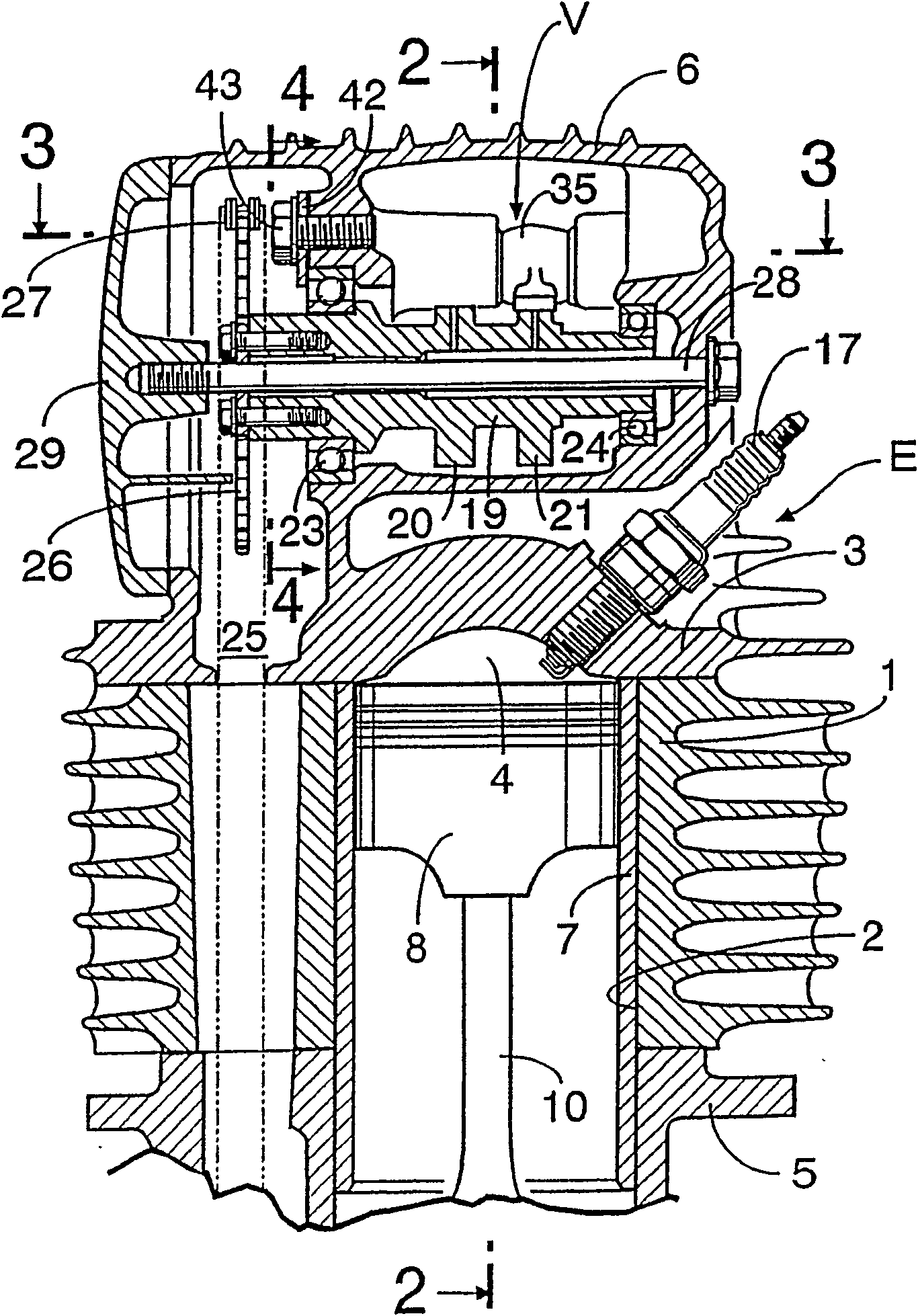
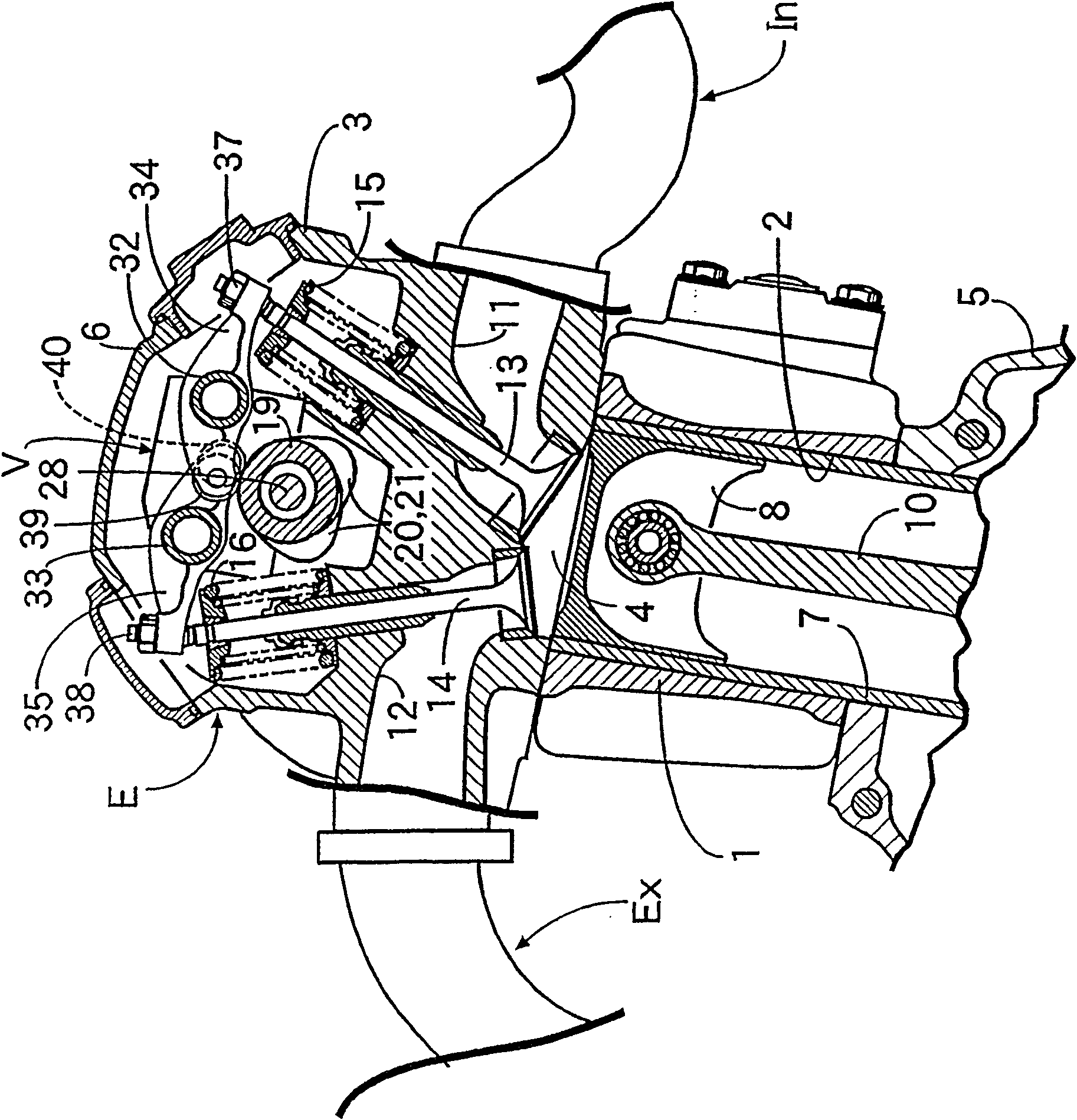
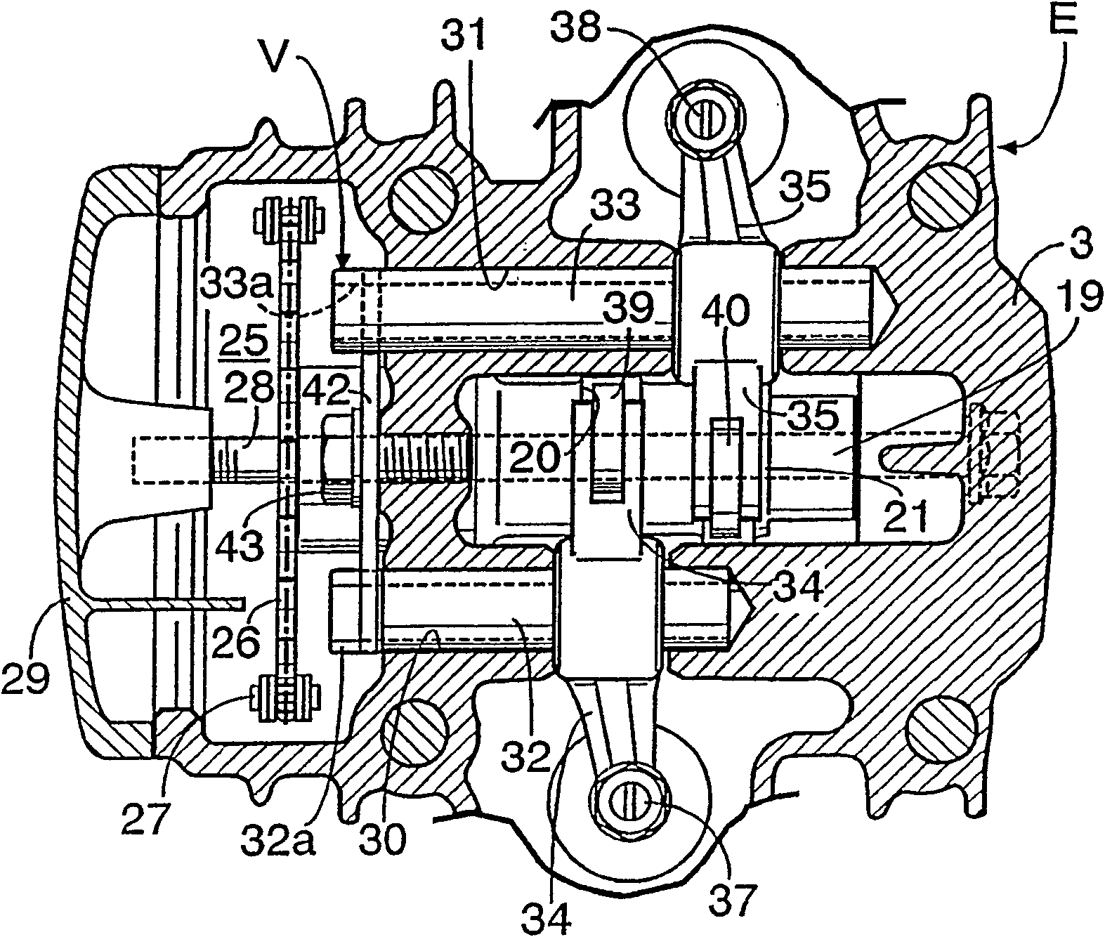
[0019] figure 1 , 2 Among them, the main body E of the SOHC type air-cooled four-stroke internal combustion engine has the following components: a cylinder block 1 provided with a cylinder bore 2; a cylinder head 3 fixed on the top surface of the cylinder block 1 to form a combustion chamber 4 opposite to the cylinder bore 2 ; Crankcase 5 fixed on cylinder block 1 below. A valve device V which will be described in detail later is provided on the cylinder head 3 , and a cylinder head cover 6 covering the valve device V is placed on the cylinder head 3 . Piston 8 is contained in above-mentioned cylinder barrel 2 through cylinder liner 7, can slide freely, and this piston 8 is connected on the crankshaft not shown in the figure through conne...


PUM


Abstract

A valve mechanism for internal combustion engines, comprising two rocker arm shafts disposed on a cylinder head, and a rocker arm rockably supported by them to operatively connect intake and exhaust cams to intake and exhaust valves, wherein a whirl-stop plate (42) is clamped and fixed to a cylinder head (3) between the two rocker arm shafts (32, 33) by a clamping bolt (43), and engaging portions (42c, 42d) formed forwardly of the clam rotation direction (a) of the first and second arm portions (42a, 42b) of the whirl-stop plate (42) are respectively engaged with engaged portions (32a, 33a) formed in the two rocker arm shafts (32, 33). Thereby, the whirl-stop of the two rocker arm shafts can be reliably effected.

Description

technical field [0001] The invention relates to an anti-rotation device of two rocker shafts in a valve gear of an internal combustion engine. The two rocker shafts support swingable rocker arms connected with intake and exhaust cams and intake and exhaust valves. Background technique [0002] Usually, in the valve gear of an internal combustion engine such as an overhead single camshaft (SOHC) type, two rocker shafts are arranged side by side on the cylinder head of the main body of the internal combustion engine at intervals. The rocker arm that can swing on the top connects the intake and exhaust cams with the intake and exhaust valves, and with the help of the rotation of the intake and exhaust cams, the above intake and exhaust valves perform switching actions within a specified time ( For example, see Japanese Patent Laid-Open No. 2000-329002). [0003] However, in this valve gear, the two rocker shafts above the valve camshaft are supported by being pressed into the ...

Claims


Application Information

Patent Timeline
IPC IPC(8): F01L1/18F01L1/02F01L1/053F01L1/46F16B1/02
CPCF01L1/022F01L2105/02F01L1/02F01L1/181F01L1/053F01L1/46F01L1/182F01L2305/02F01L1/18
Inventor 阿久津敏治横山充石坂孝史
Owner HONDA MOTOR CO LTD
Why Eureka
Try Eureka