Lawn mower

A technology for lawn mowers and cutting objects, which is applied in the directions of harvesters, cutters, agricultural machinery and implements, etc., can solve the problem of the large volume of receiving baskets, and achieve the effect of reducing noise level, reducing overall size and saving energy.

Inactive Publication Date: 2009-04-15
克劳斯·费切勒
View PDF2 Cites 17 Cited by
  • Summary
  • Abstract
  • Description
  • Claims
  • Application Information

AI Technical Summary

Problems solved by technology

However, the disadvantage of this arrangement is that the receiving basket must be located in the conceivable throwing direction of the cuttings, usually on the side of the lawn mower facing the user of the lawn mower
However, this leads to a bulky arrangement of the receiving basket, which often constitutes an obstacle within the foot reach of the user of the lawnmower

Method used


Image

  • Lawn mower
  • Lawn mower
  • Lawn mower

Examples


Embodiment Construction

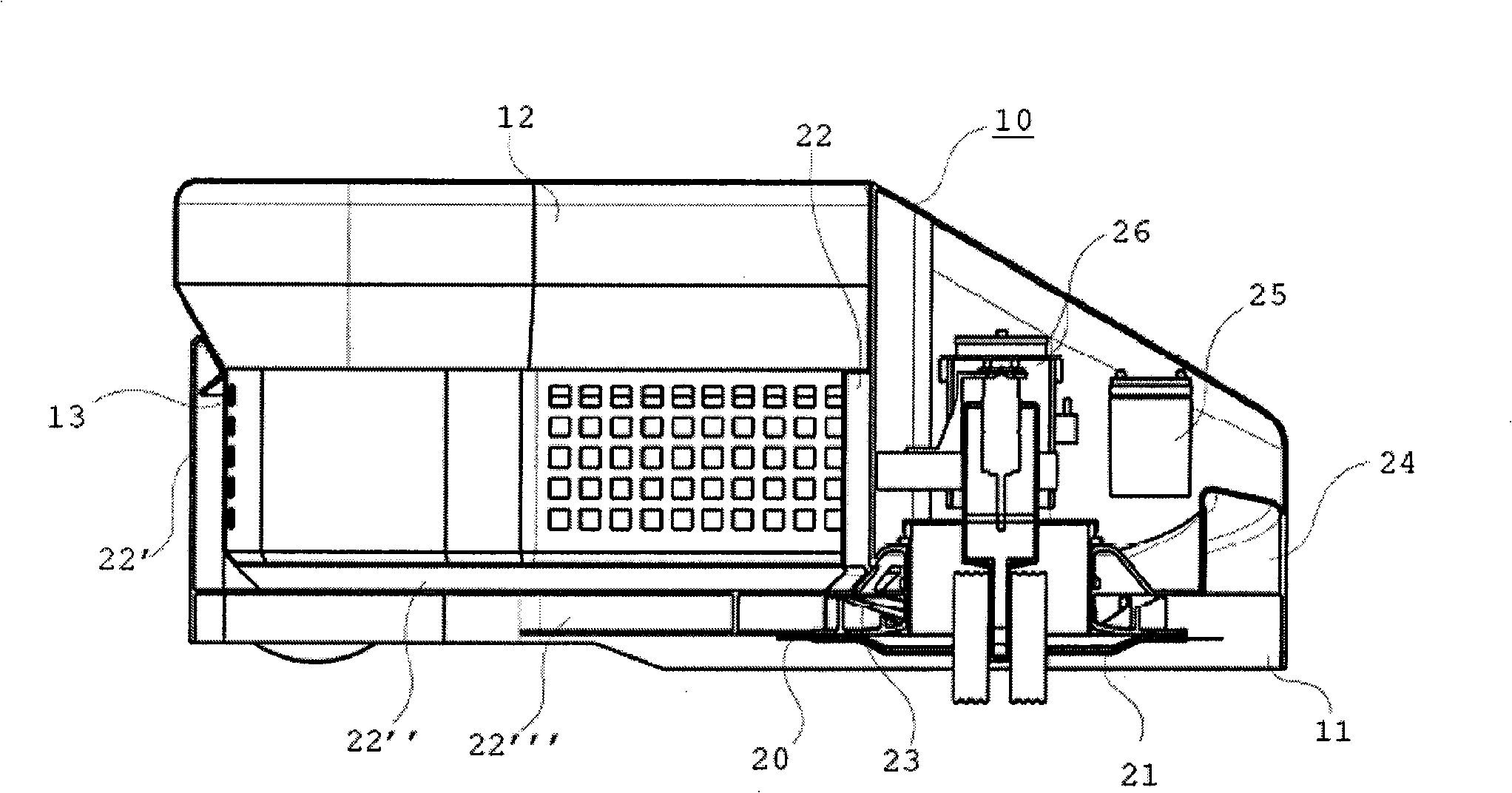
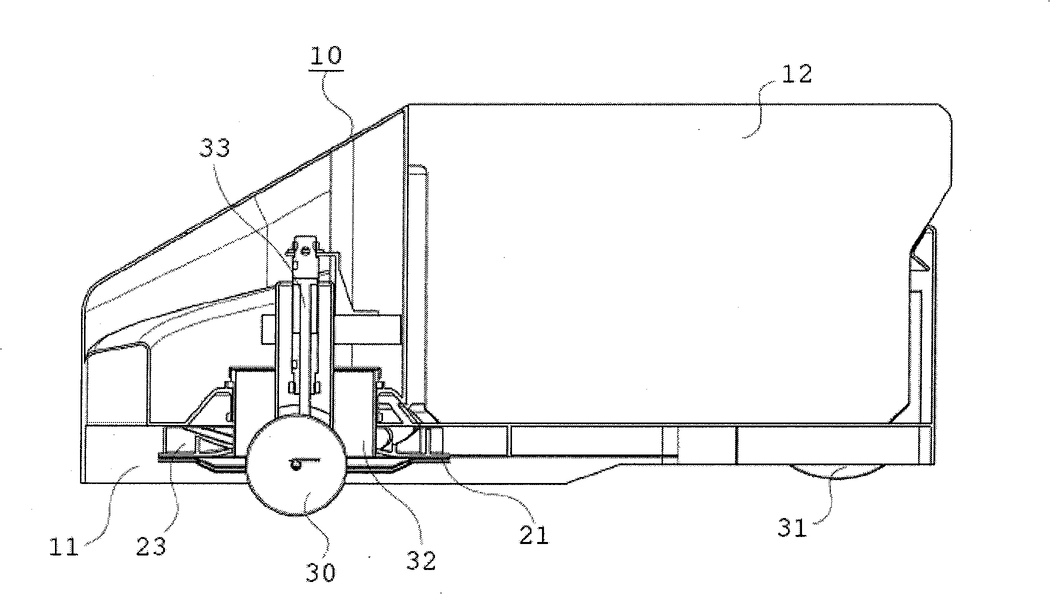
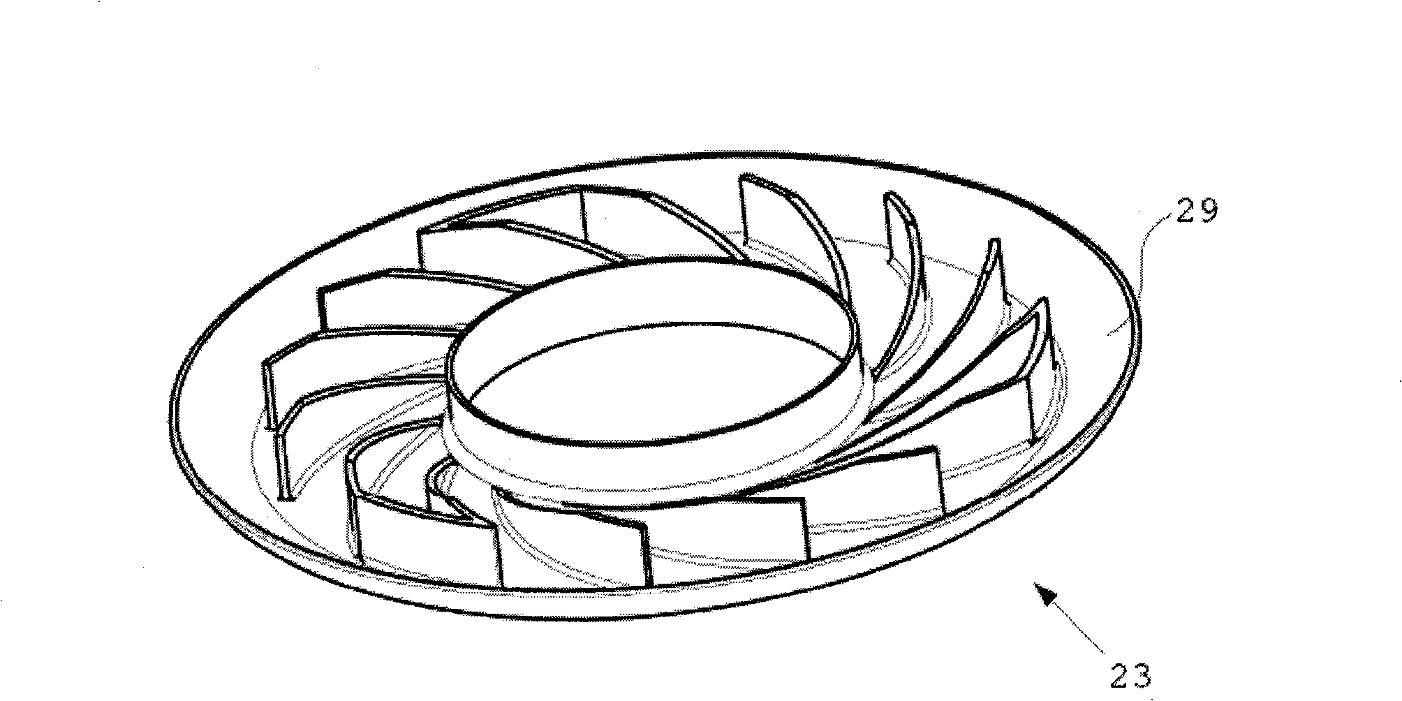
[0054] figure 1 A lawnmower is shown with a housing 10 which substantially surrounds a mowing chamber 11 and a collection container 12 . A cutterhead 21 is provided in the mowing chamber 11, and the cutterhead cuts the grass on the lawn surface where the mower acts within the region of the cutterhead 21 when the mower is running. The cutter head 21 is designed circular here, so that a deflection wheel 30 passing through the cutter head can be arranged in the center of the cutter head 21 . A plurality of blades 20 are mounted in the cutterhead 21, the number of blades being replaceable depending on the actual required usage possibilities of the mower. For example for topsoil mulching, a higher number of blades can be used, and if necessary multiple blades can be installed in multiple planes using multiple blade assemblies, conversely, when simply mowing the lawn, a higher number of blades can be used. Small number of blades 20. against Figure 7 The instructions explain the...


PUM


Abstract

A prior lawn mower uses the negative-pressure produced in a collecting container to suck the object to be cut, and then sends the cut object into a collecting container. To this end, a fan is provided, apart from the original motor for driving the cutter, the fan should additionally have a motor. The known lawn mower should be improved. The improvement is achieved by that the compression plate is concentric with the cutter and is supported all together. Therefore space is saved without using a separate fan, thus the necessary power diminishes. The noise pollution can also be reduced. The invention can be used for lawn mowing.

Description

technical field [0001] The invention relates to a lawnmower with a housing comprising a collecting container for receiving cuttings cut by a rotating cutter head, a suction channel for sucking the cuttings into the collecting container , and a suction channel for leading the sucked-in air out of the collection container, wherein the suction channel has a compression disk concentric with the cutter head and supported together with the cutter head for generating a negative pressure in the collection container . Background technique [0002] In particular, patent document DE 198 50 260 B2 has previously disclosed such a lawnmower. This patent document teaches that the lawnmower is equipped with a collection container built into the air circuit. It is also recommended that, in the traditional way, with the aid of a cutting knife ( ) separates the cuttings from the lawn surface, sucks up the separated cuttings by means of an air flow and makes them finally enter a collection ...

Claims


Application Information

Patent Timeline
Patent Type & Authority Applications(China)
IPC IPC(8): A01D43/063A01D43/077A01D34/73A01D34/74A01D43/08A01D43/14
CPCA01D43/077A01D43/063
Inventor 克劳斯·费切勒
Owner 克劳斯·费切勒
Why Eureka
Try Eureka