
Peristatic pump with a removable and deformable carrier

A peristaltic pump, supporting surface technology, used in the field of peristaltic pumps

Inactive Publication Date: 2009-04-22
ATHENA INNOVATIONS
View PDF0 Cites 21 Cited by
  • Summary
  • Abstract
  • Description
  • Claims
  • Application Information

AI Technical Summary

Problems solved by technology

[0016] The described peristaltic pump is not manufactured for delicate laboratory or medical applications, the curvature of the ring and the means to obtain the curvature by twisting the bolts are not described

Method used


Image

  • Peristatic pump with a removable and deformable carrier
  • Peristatic pump with a removable and deformable carrier
  • Peristatic pump with a removable and deformable carrier

Examples


Embodiment Construction

[0049] A presently preferred embodiment of a peristaltic pump according to the invention will now be described with reference to the accompanying drawings.

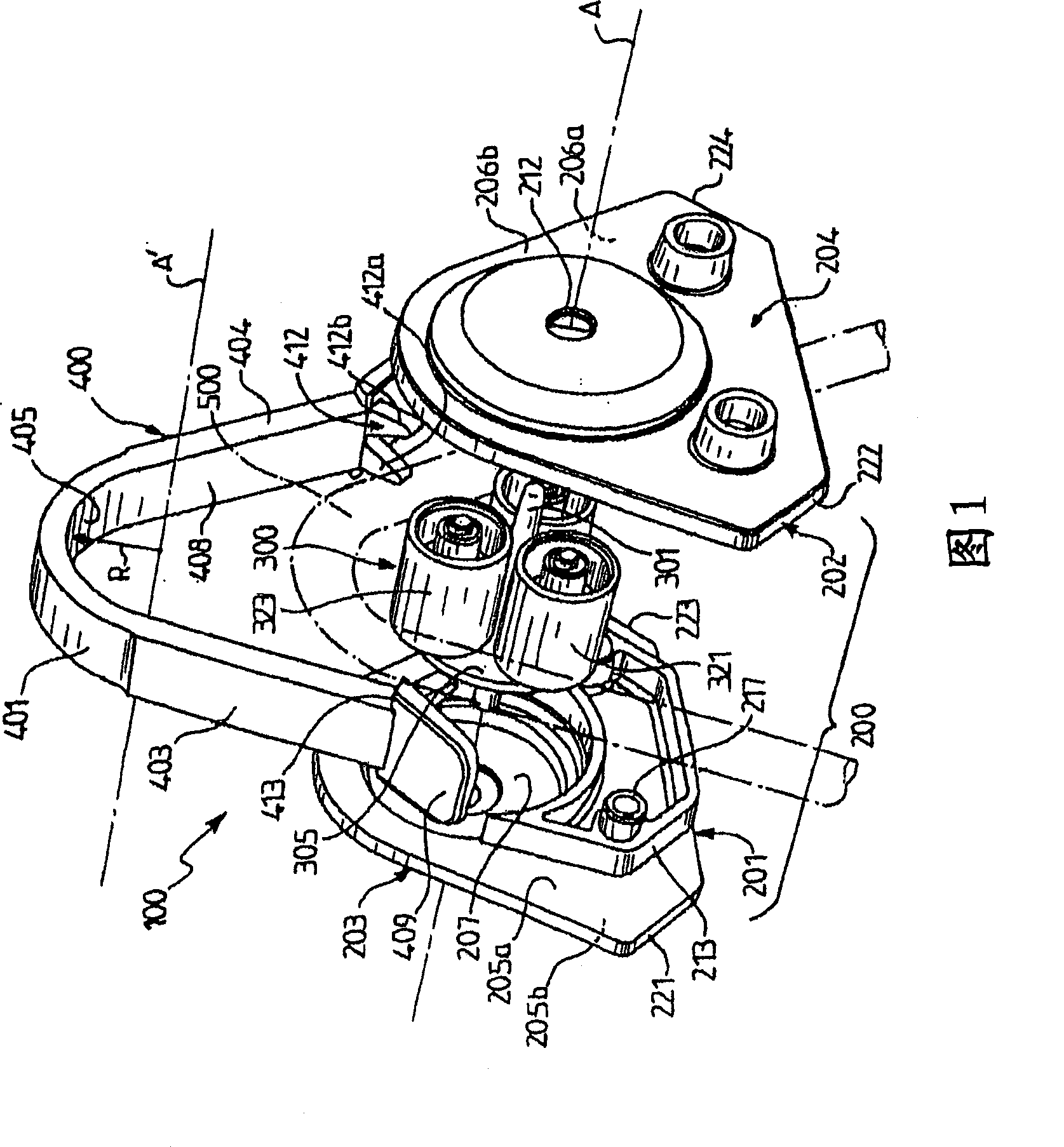
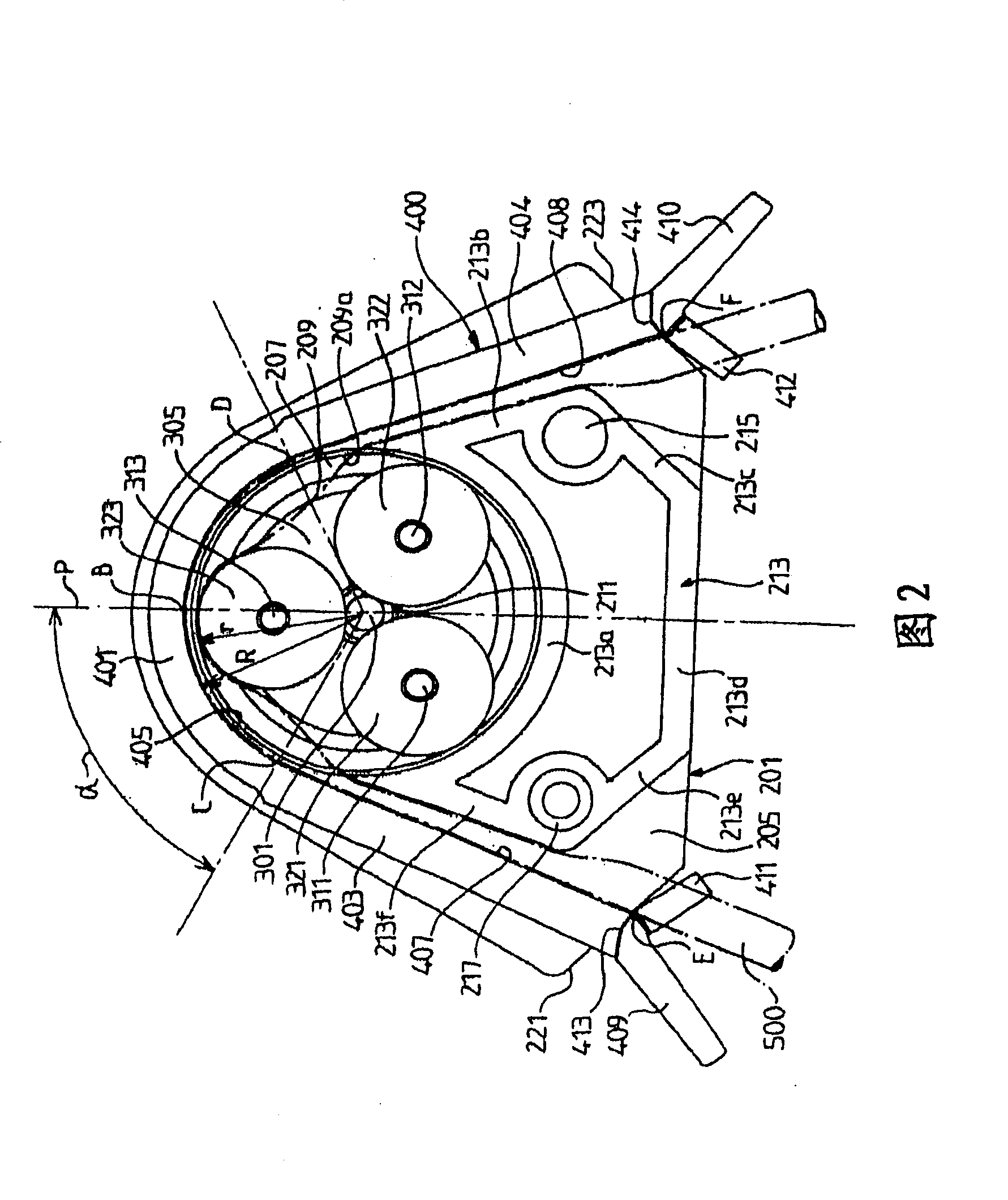
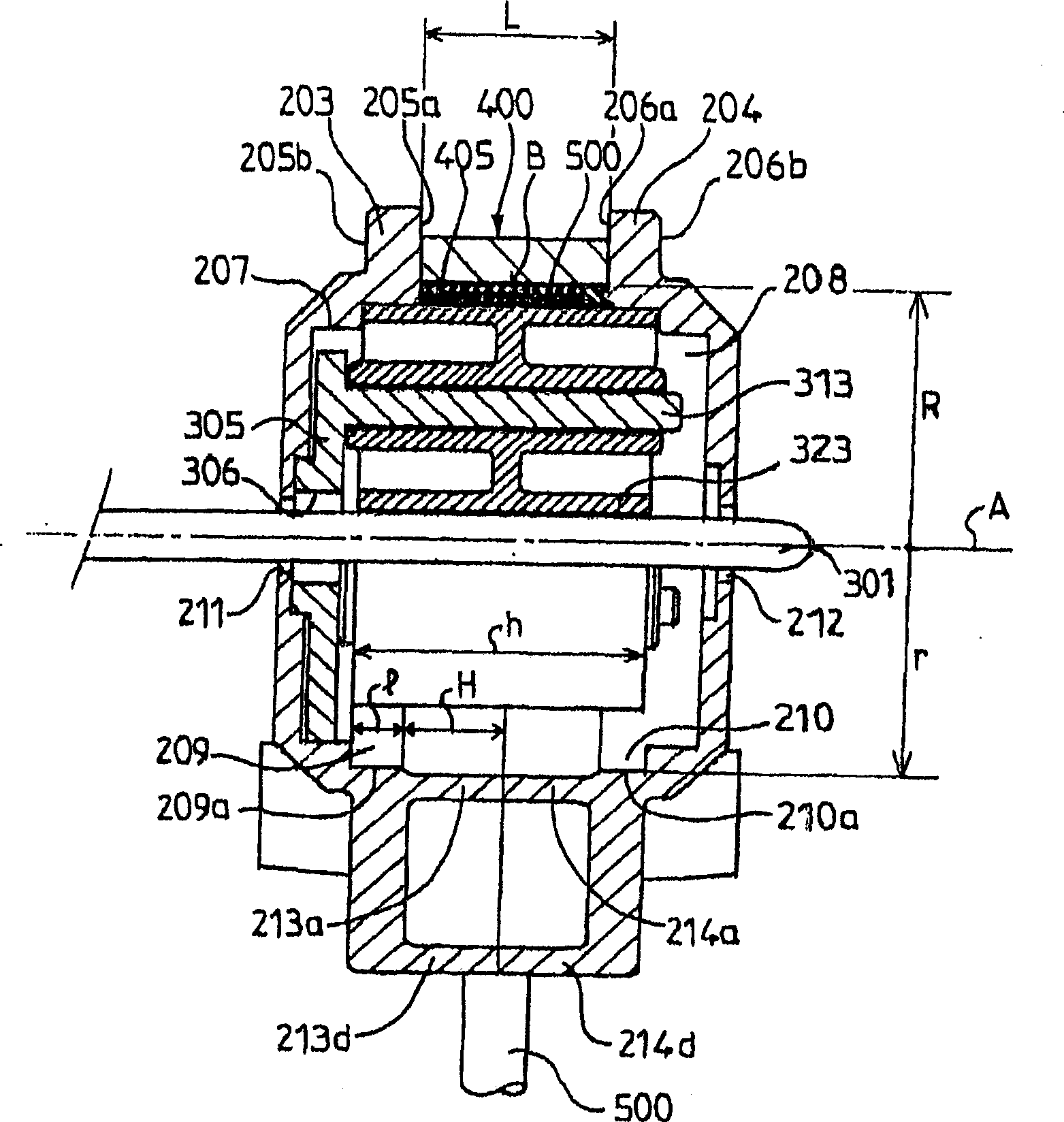
[0050] 1 to 3, the peristaltic pump 100 includes a housing 200, a driving device 300, a movable support surface 400 and a deformable pump body tube 500 (shown by a dotted line in FIG. 2).

[0051] The housing 200 includes a first half shell 201 and a second half shell 202 . The first half-shell and the second half-shell are identical. If they are made of plastic, as in the presently preferred embodiment, each of the two half-shells can be molded using a separate mould.

[0052] The first half shell 20 will now be described in detail. Everything that will be said about the first half shell 201 applies equally to the second half shell 202 . Accordingly, each element of the second half-shell 202 is labeled with a similar number as the corresponding element of the first half-shell 201, but increased by one.

[0053] The f...


PUM


Abstract

The inventive peristaltic pump (100) comprises a removable carrier (400) against which a flexible tube is pressed by rollers. Said carrier (400) comprises an intermediate deformable section (401) having an internal cylindrical surface (405) whose axis (A) coincides with the main axis of rotation of the rollers and lateral rigid arms (403, 404) arranged on both sides of said intermediate section. The free ends (E, F) of the lateral arms comprise guiding means (412, 414), respectively. The pump case is provided with paths on which said guiding means are slidable. The path directions are predefined in order to constrain the displacement of the free ends of the lateral arms and to deform the intermediate section in such a way that the radius of the internal face is modified keeping the axis thereof coinciding with the main axis, thereby making it possible to use a tube having variable characteristics for said peristaltic pump.

Description

technical field [0001] The invention relates to peristaltic pumps with deformable tubes. Background technique [0002] Generally, peristaltic pumps comprise a frame to which is fixed a motor, the shaft of which rotates a housing comprising a number of rollers. The rollers are in contact with the deformable tube, and the rollers squeeze the deformable tube until it is sealed. The angular displacement of the sealing point creates a vacuum in the tube after the pinch zone, which vacuum of the tube is immediately filled with liquid. The amount of fluid collected between the two rollers in the deformable tube is then pushed to the outlet of the pump. Liquid pumped at the open end of the deformable tube is delivered to the other end of the deformable tube. The open end is called the inlet or upstream end and the other end is called the delivery or downstream end. Most peristaltic pumps consist of a housing with a cylindrical inner surface, called a bearing surface, against whi...

Claims


Application Information

Patent Timeline
Patent Type & Authority Applications(China)
IPC IPC(8): F04B43/12
CPCF04B43/1253F04B43/1284
Inventor B·马尔贝克让-马里·佩罗
Owner ATHENA INNOVATIONS
Learn More