
Method of hydrolytically stable bonding of elastomers to substrates

Active Publication Date: 2011-08-11
MASSACHUSETTS INST OF TECH
View PDF6 Cites 70 Cited by
  • Summary
  • Abstract
  • Description
  • Claims
  • Application Information

AI Technical Summary

Benefits of technology

[0024]In one embodiment, the hydrolytic stability is achieved by depositing the molecule onto the first surface through immersion of the surface in a solution containing the molecule and optionally containing a chemical which causes hydrolysis of unwanted weak bonds.

Problems solved by technology

However, for microfluidic structures requiring dimensional stability, rigidity, or disposability, PDMS is not the preferred candidate.
However, it was found that exposing monolayer primer coatings to plasma bonding processes resulted in degradation of the silane films, leading to DI water induced bond failure and delamination under pressure conditions below 15 psi.
Also, data on bond strength in aqueous and chemically harsh environments is not available for the published processes.
Direct glass deposition processes are high temperature activated or plasma activated, which can lead to plastic substrate breakdown.
In addition, direct glass deposition onto plastic substrates leads to bonds which hydrolyze readily upon exposure to moisture.
However, bond chemistry between this primer and organic surfaces is non-ideal due to oxygen coupled bonds and the lack of long-term hydrolytic stability in aqueous environments, with the majority of the primer consisting of a titanium alkoxide, which readily absorbs water molecules.
Bonding of these coatings to PDMS has also been demonstrated, but hydrolytic stability was not tested.
While amine functional silanes have been demonstrated to react directly with certain substrates such as PC and PMMA, prolonged treatment times necessary to generate a reasonable surface bond density as well as substrate selective chemistry make such a process not generally useful.
For activated organic substrates, silane alkoxy group hydrolysis into silanols poses a major problem.
Any contact with water after bond formation will result in Si—O—C bond hydrolysis and ultimately bond failure.
However, networks formed by typical silanes, containing three silanol groups, tend to be cyclic, decreasing their resistance to dissolution.

Method used


Image

  • Method of hydrolytically stable bonding of elastomers to substrates
  • Method of hydrolytically stable bonding of elastomers to substrates
  • Method of hydrolytically stable bonding of elastomers to substrates

Examples


example 1

A Molecule Comprising Two Silane-Derivative Groups for Enhanced Bonding of Elastomer to Plastic

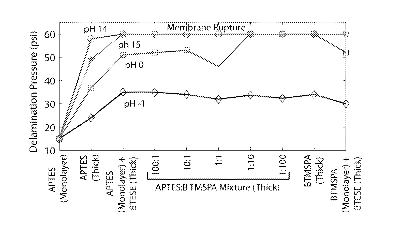
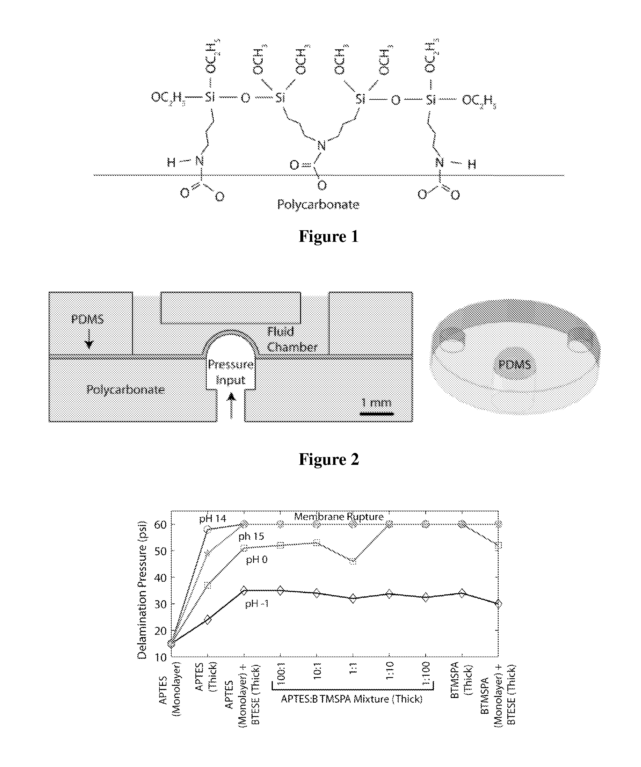
[0163]Two molecules containing bis-silanes derivatives were investigated for improving bond strength: BisTriEthoxySilylEthane (BTESE) and Bis(TriMethoxySilylPropyl)Amine (BTMSPA). For BTESE, primers consisted of a two step process, wherein a molecule bearing one functional silane-derivative was first coated onto the plastic substrate for covalent bonding. This step was followed by coating with BTESE. Separately, in a one step coating process, a mixture of two molecules was used. The mixture contained one molecule bearing one functional silane-derivative and one molecule bearing two-functional silane-derivative molecule. The molecule bearing one silane-derivative was APTES and the molecule bearing two silane-derivative was Bis(TriMethoxySilylPropyl)Amine (BTMSPA). Coating a substrate by this mixture resulted in a thick single step coating. The coating layers were explored for its effects on...


PUM

PropertyMeasurementUnit
Temperatureaaaaaaaaaa
Timeaaaaaaaaaa
Timeaaaaaaaaaa

Abstract

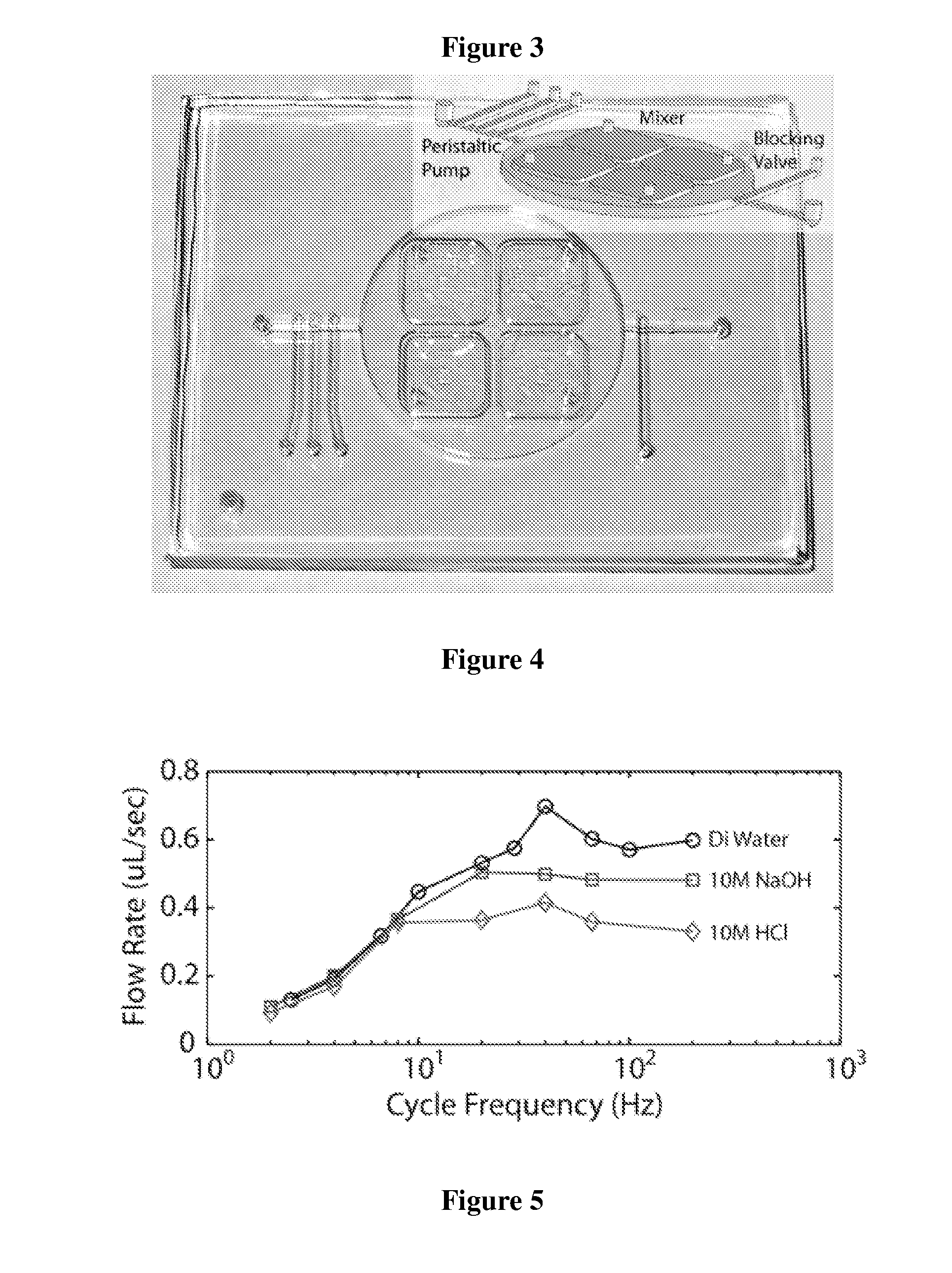
Active devices such as pumps and mixers have been fabricated in plastic-PDMS hybrid devices. By utilizing functionalized bis-silane primers, bond strength between Polycarbonate or PMMA and PDMS improved in dry and aqueous environments. Plastic-primer-PDMS layers exposed to acid and base solutions at 70° C. for 2 hours showed no signs of delamination at 30 psi for pH −1 to 15 and 60 psi for pH 0 to 15. A peristaltic pump fabricated in polycarbonate achieved consistent flow rates up to peristaltic cycle frequencies of 10 Hz in water, 1OM HCl, and 1OM NaOH solutions.

Description

BACKGROUND OF THE INVENTION[0001]PDMS is a common material for fabrication of microfluidic devices. Elasticity provided by PDMS enables the formation of active devices which can utilize pressurized membranes such as pumps and mixers. However, for microfluidic structures requiring dimensional stability, rigidity, or disposability, PDMS is not the preferred candidate. Such properties are provided by plastics.[0002]Plastics can be manufactured using mass fabrication technologies such as injection molding and hot embossing with well established bonding processes but at the cost of sacrificing active device functionality. Therefore a combination of PDMS and plastics is desirable in the fabrication processes of microfluidic devices in order to gain the advantages of both materials as described above. Fabrication process combining plastic substrates with PDMS membranes enables the formation of active microfluidic devices inside dimensionally stable systems, merging the functionality of PDM...

Claims


Application Information

Patent Timeline
IPC IPC(8): B32B9/04B32B37/02B32B37/06B32B37/12B32B37/16B01L3/00G01N33/48C07F7/08C09D7/00B82Y99/00
CPCB29C65/8207B29C65/8223B29C66/02B29C66/026B29C66/7463B29C66/7465B29K2025/00B29K2033/12B29K2069/00B29K2309/08B29K2309/10B29L2031/756B81B2201/058B81C3/001B81C2201/019C08J5/12C08J2325/06C08J2333/12C08J2369/00C09J5/00C09J2400/123C09J2400/143B29C65/8246B29C65/00Y10T428/31663
Inventor LEE, S. KEVINLEE, HARRYRAM, J. RAJEEV
Owner MASSACHUSETTS INST OF TECH
Learn More