

Method for producing thermally tempered glasses
a technology of thermal tempered glass and glass, which is applied in the direction of glass tempering apparatus, glass making apparatus, glass shaping apparatus, etc., can solve the problems of temperature gradient and glass destruction, and achieve the effect of increasing the glass strength
- Summary
- Abstract
- Description
- Claims
- Application Information
AI Technical Summary
Benefits of technology
Problems solved by technology
Method used
Image

Examples
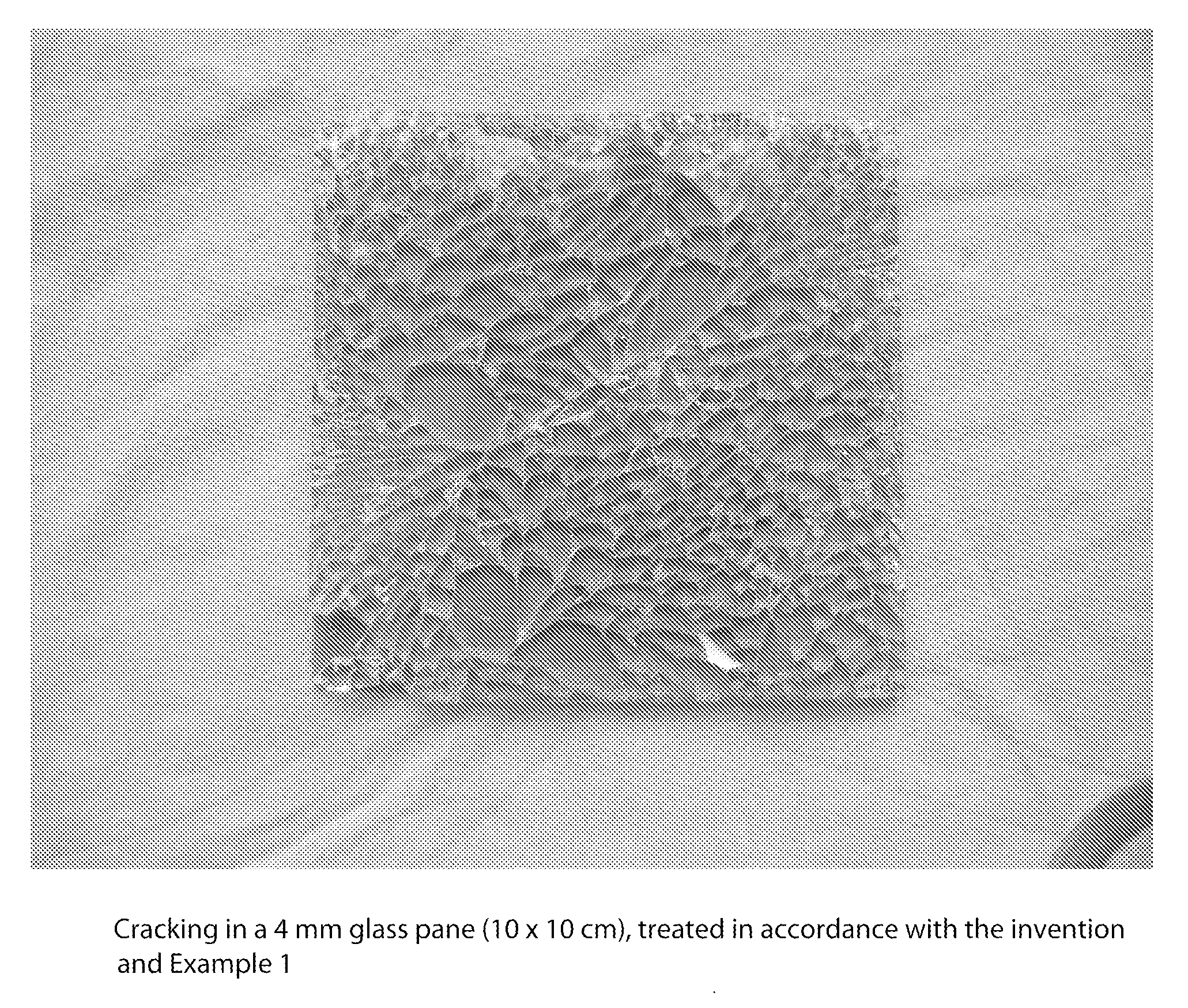
example 1
[0032]A float glass pane based on commercial soda-lime silicate glass, having a thickness of 4 mm and cut to size by laser cutting, is heated to an integral temperature of 680° C. and cooled, after removal from the furnace, by spray cooling on both sides for a maximum of 30 seconds using 11 / minute on a surface measuring 2 by 100 cm2. The picture of cracking shown in FIG. 1 is obtained using a standard, commercially available impact punch tool. A similar pane of float glass not cut to size by laser cutting broke when spray cooling was applied.
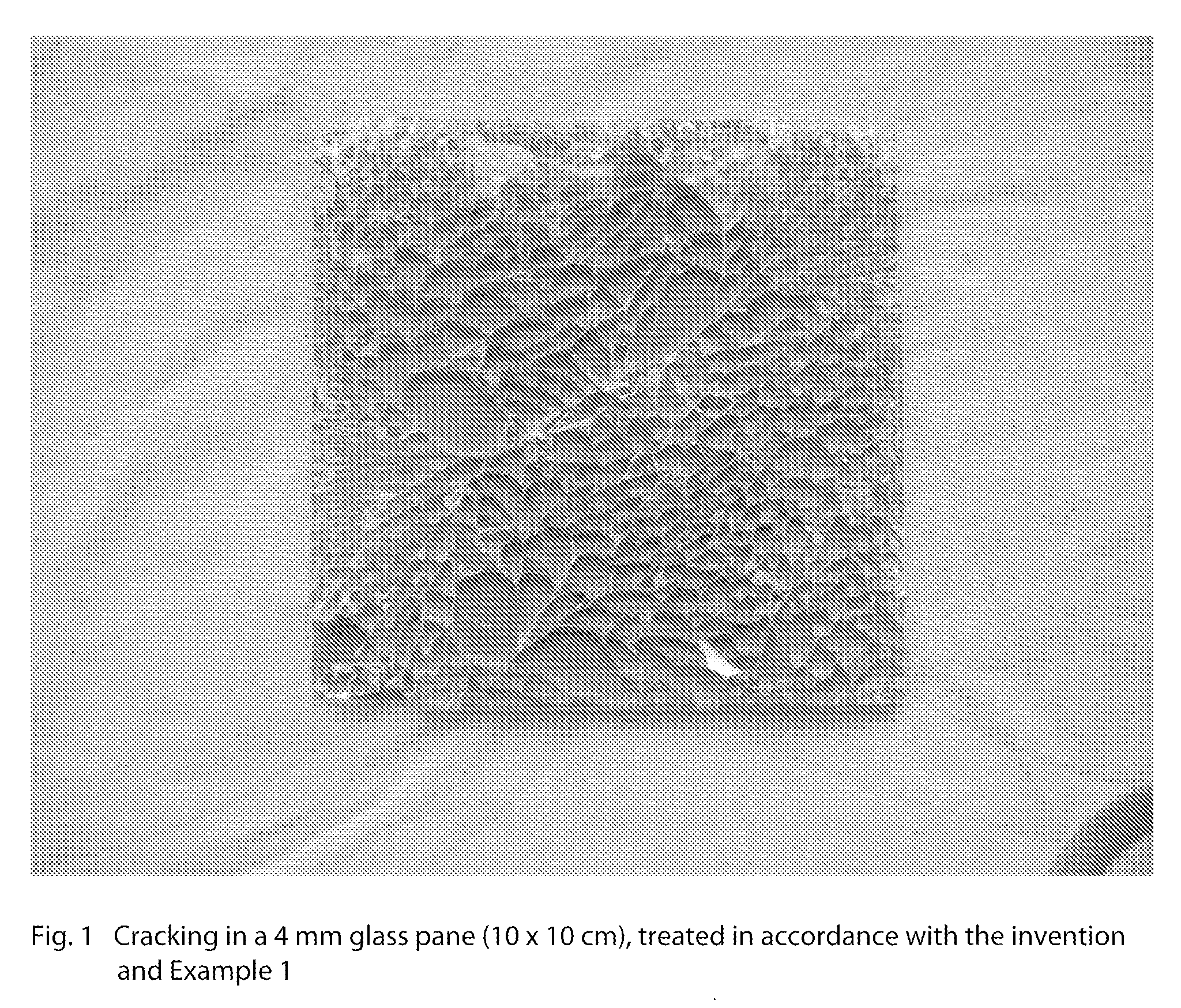
example 2
[0033]A float glass pane based on commercial soda-lime silicate glass, having a thickness of 2 mm and cut to size by laser cutting, is heated to an integral temperature of 680° C. and cooled, after removal from the furnace, by spray cooling on both sides for a maximum of 30 seconds using 2 I / minute on a surface measuring 2 by 100 cm2.
[0034]The defects shown in FIG. 2 is obtained using a standard, commercially available impact punch tool. A similar pane of float glass not cut to size by laser cutting broke when spray cooling was applied.
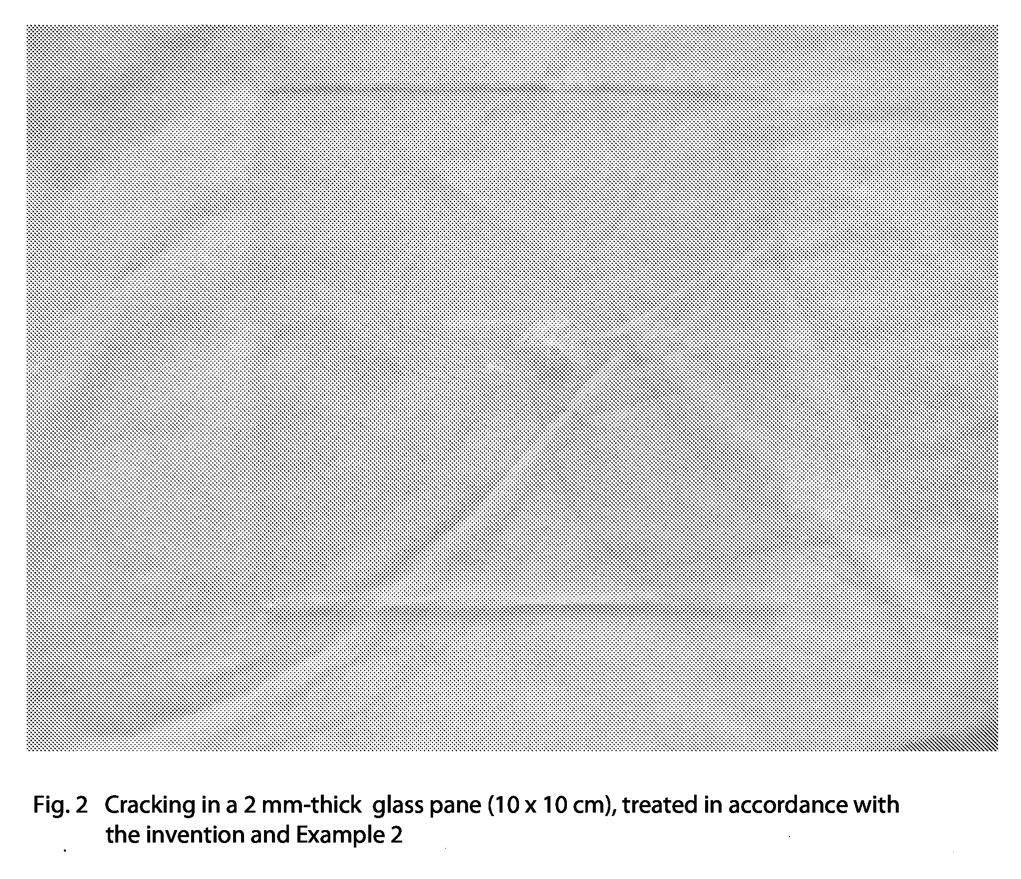
example 3
[0035]A pane of float glass on a commercial soda-lime silicate glass basis with a thickness of 2 mm, cut to size by laser cutting, is heated to an integral temperature of 680° C. Treatment with aluminium chloride is carried out simultaneously with heating. After the glass has been removed from the furnace, it is cooled by spray cooling both sides for a maximum of 30 seconds using 4 l / minute on a surface measuring 2 by 100 cm2. The fracture image shown in FIG. 3 is obtained using a standard, commercially available impact punch tool. A similar pane of float glass not cut to size by laser cutting broke when spray cooling was applied.
[0036]The following examples describe the method according to the particularly preferred development of the invention.
[0037]FIG. 4 shows the principle of a system for thermally tempering according to the particularly preferred method. A particularly advantageous variant of the method is one in which two plate coolers are combined as a tandem system by alter...
PUM
| Property | Measurement | Unit |
|---|---|---|
| heat transfer coefficient | aaaaa | aaaaa |
| thickness | aaaaa | aaaaa |
| thickness | aaaaa | aaaaa |
Abstract
Description
Claims
Application Information