Ultrasound receive beamformer

A technology of receiving beams and formers, which is applied in ultrasonic/acoustic/infrasonic diagnostics, sounding devices, acoustic diagnostics, etc., and can solve problems such as inapplicable parallel beams

Inactive Publication Date: 2009-05-13
ALOKA CO LTD
View PDF0 Cites 14 Cited by
  • Summary
  • Abstract
  • Description
  • Claims
  • Application Information

AI Technical Summary

Problems solved by technology

However, this method only works when the beam is not being steered, not for parallel beams

Method used


Image

  • Ultrasound receive beamformer
  • Ultrasound receive beamformer
  • Ultrasound receive beamformer

Examples


Embodiment Construction

[0021] Embodiments of the present invention will be described in detail below with reference to the accompanying drawings, wherein like reference numerals designate like elements throughout. Before embodiments of the invention are described in detail, it is to be understood, however, that the invention is not limited in its application to the details set forth in the following description or the examples shown in the accompanying drawings. The present invention can also implement or carry out other embodiments in various applications or in various ways. Also, it is to be understood that the phraseology and terminology used herein are for the purpose of description and should not be regarded as limiting. As used herein, "comprises," "comprising," or "having" and other variations thereof, is meant to encompass the items listed thereafter and equivalents thereof as well as additional items. The terms "mounting", "connecting" and "coupling" are used broadly to encompass both dire...


PUM


Abstract

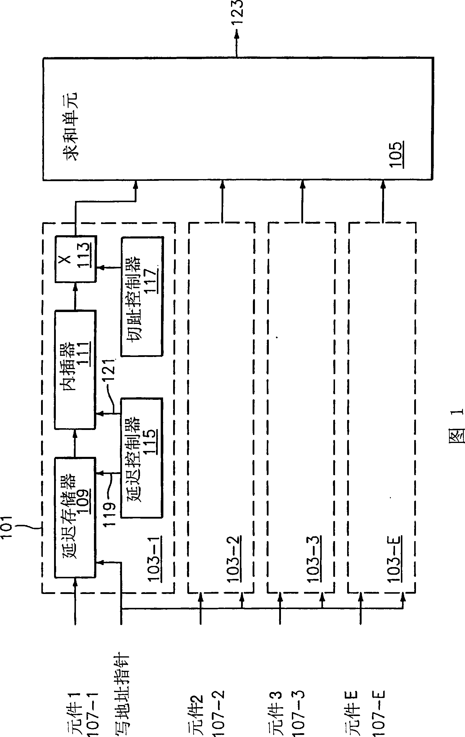
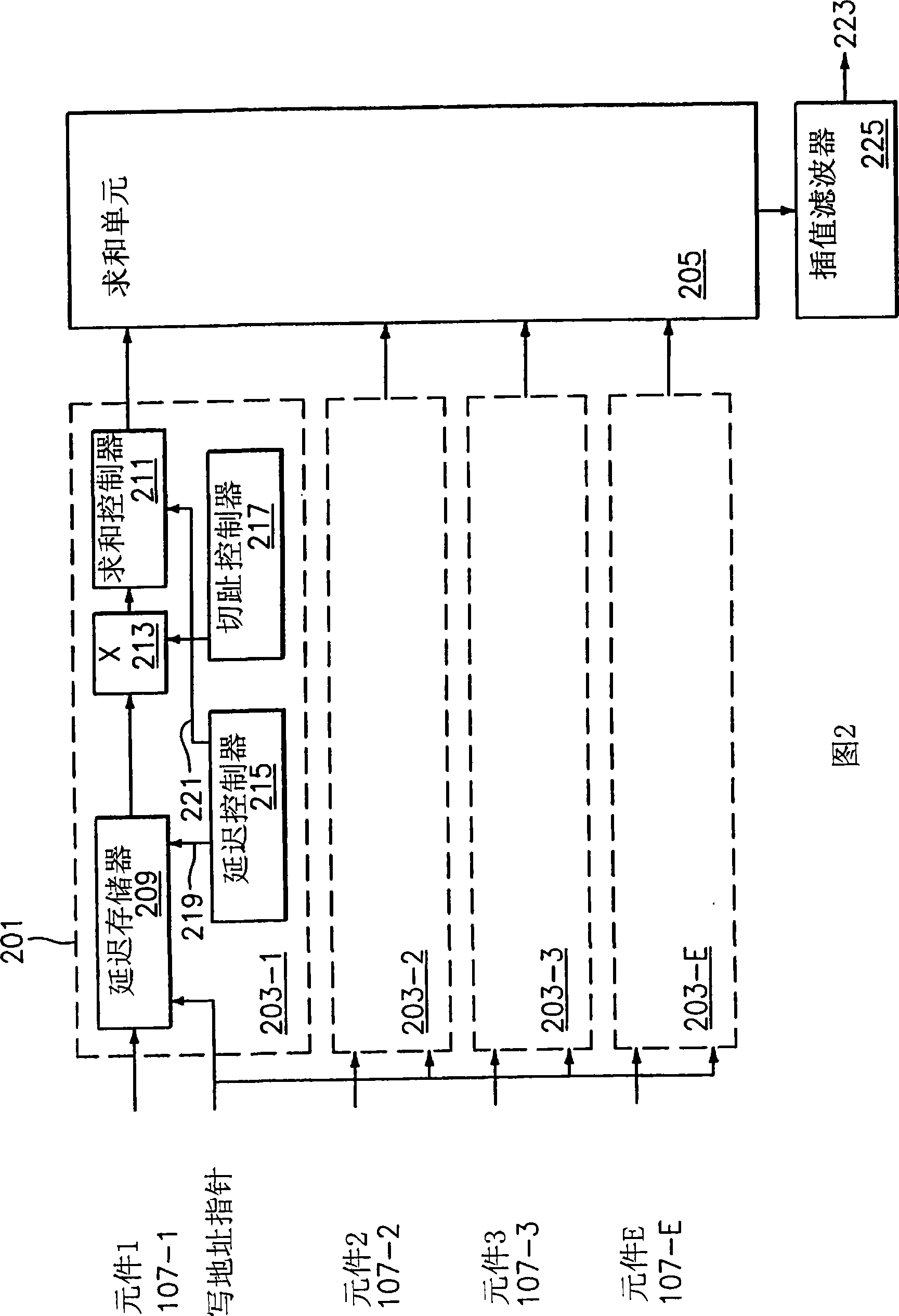
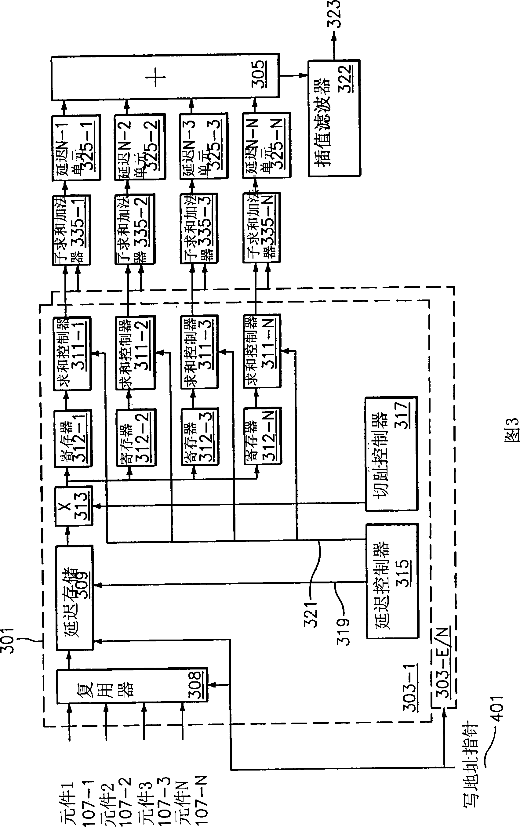
In an ultrasound receive beamformer signals from two or more aperture elements are multiplexed at the input of each beamformer channel, stored in different portions of a delay memory, delayed and apodized in a time-multiplexed fashion, demultiplexed at the output of the channel, and summed in different summation units running at an upsampled rate. The partial sums are then time-aligned, summed toproduce the total upsampled beam sum, filtered and decimated in an interpolation filter to produce the beamformed signal.

Description

technical field [0001] The present invention generally relates to ultrasound image processing. More specifically, embodiments of the invention relate to systems and methods for focusing received ultrasound beams. Background technique [0002] With ultrasound imaging, a transducer is used to send an ultrasound beam into the medium to be examined, such as the human body. Ultrasonic beams are reflected at various cross-sections in certain parts of the human body. The received ultrasound echoes are converted into electrical signals, which go through multiple processing steps and finally converted into images that can be displayed or printed for inspection. [0003] Transducers Ultrasonic transducers are arrays of small rectangular piezoelectric elements. A subset of elements in the array are used to transmit or receive ultrasound beams, called the transmit or receive apertures, respectively. The signal received by each element within the aperture is amplified and filtered an...

Claims


Application Information

Patent Timeline
Patent Type & Authority Applications(China)
IPC IPC(8): A61B8/00
CPCG10K11/346G03B42/06
Inventor R·亚历山德鲁
Owner ALOKA CO LTD
Why Eureka
Try Eureka