Image forming apparatus having plural image supporting bodies

Inactive Publication Date: 2007-05-29
CANON KK
View PDF7 Cites 7 Cited by
  • Summary
  • Abstract
  • Description
  • Claims
  • Application Information

AI Technical Summary

Benefits of technology

[0013]An object of the present invention is to provide an image forming apparatus which eliminated

Problems solved by technology

However, since the conventional 4D printer is equipped merely with a single set of delay memories, even if a sheet size (image size) is changed while a series of recor

Method used


Image

  • Image forming apparatus having plural image supporting bodies
  • Image forming apparatus having plural image supporting bodies
  • Image forming apparatus having plural image supporting bodies

Examples


first embodiment

(First Embodiment)

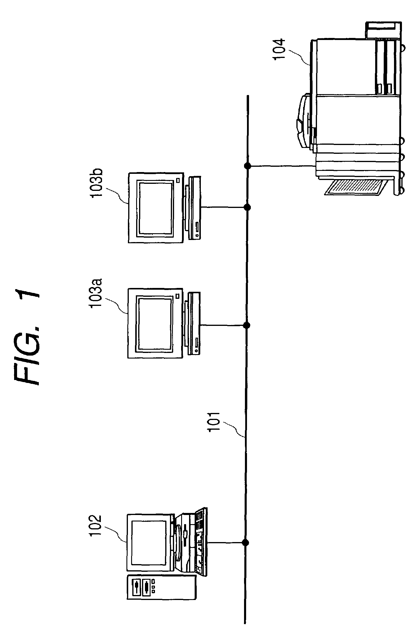
[0039]FIG. 1 is a block diagram showing an image forming system according to the first embodiment of the present invention. In FIG. 1, a computer 102 is a server which is connected to a network 101, and computers 103a and 103b are clients which are also connected to the network 101. Although it is not shown in FIG. 1, it should be noted that a lot of other clients are connected to the network 101, and all of these clients are representatively called a client 103 hereinafter.

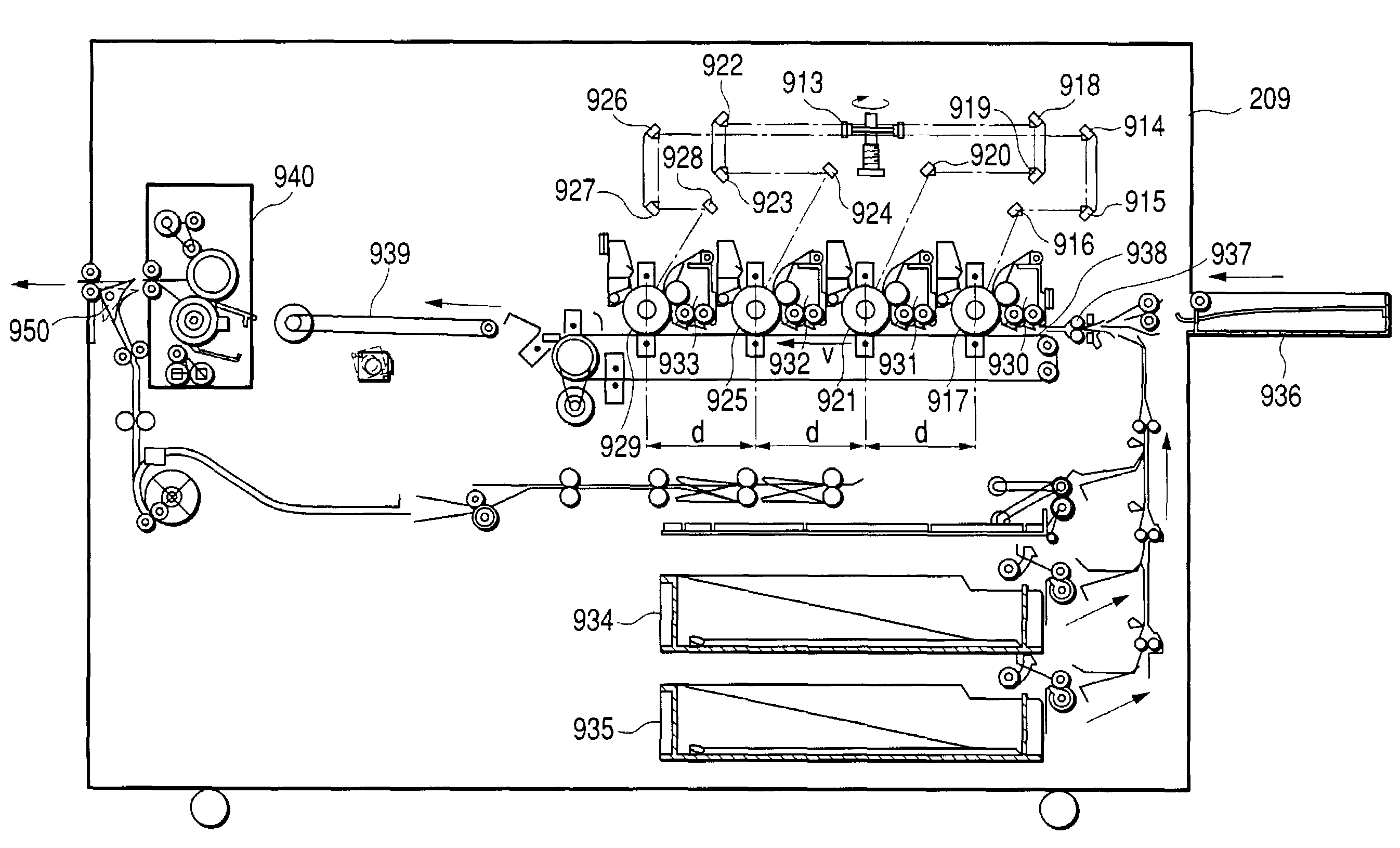
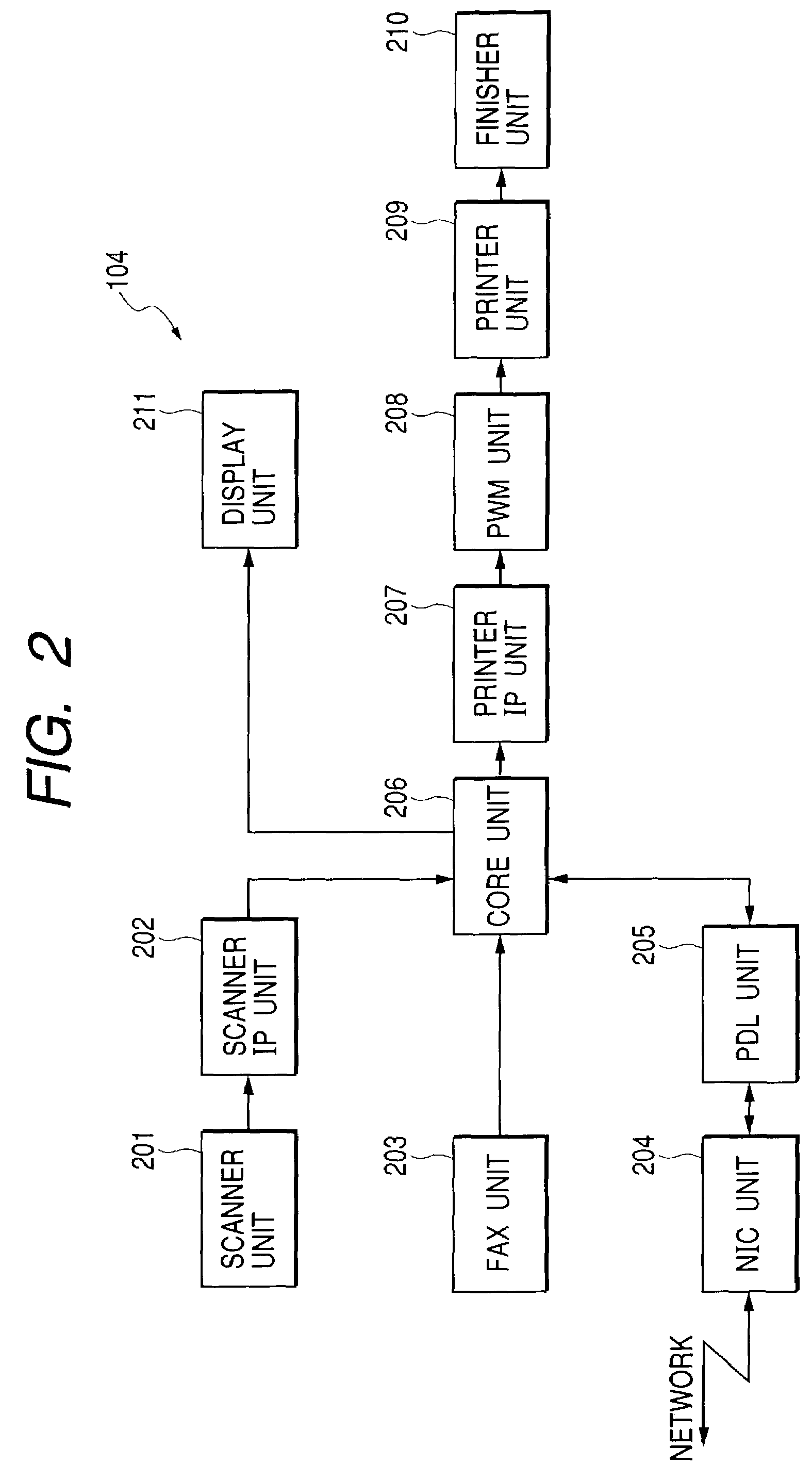
[0040]Moreover, an MFP 104 which is a color-four-drum MFP capable of performing full-color image reading, full-color printing, facsimile transmission, facsimile reception and the like is connected to the network 101. Moreover, although it is not shown in FIG. 1, various other apparatuses such as another MFP, a scanner, a printer, a facsimile machine and the like are connected to the network 101.

[0041]Here, on the computer 103, application software for executing so-called DTP (Desktop Publishing)...

second embodiment

(Second Embodiment)

[0138]FIG. 18 is a timing chart showing changes of control signals of a drum delay unit 704 in its main scan direction, according to the second embodiment. It should be noted that output of 16-bit image data ram_data shown in FIG. 18 is different from that shown in FIG. 13.

[0139]Moreover, it should be noted that inputs of a sub-scan valid interval signal venb_in and four-bit image data data_in are the same as those shown in FIG. 13. The data are input for a main-scan valid interval (data_valid_p0) of the first page. In this interval, the data of 16 pixel clocks are temporarily stored as one block (data w0), and then the image data are collected into the block for every 16 clocks (data w1, data w2).

[0140]The temporarily stored image data w0, w1 and w2 are output as the data ram_data to an SDRAM 1205 in the interval of a main-scan valid interval signal henb_wr for the data writing, and the plural image data are stored in the SDRAM 1205. Here, as described above, the...

third embodiment

(Third Embodiment)

[0144]In the first and second embodiments, the data writing and the data reading to and from the memory are controlled by storing and administrating the length of the data in the main scan direction or in the sub scan direction. On one hand, memory writing and reading can be controlled also by beforehand setting an end address representing the end of the memory writing for each page. For example, in a case where the data writing and the data reading of the main scan interval to and from a memory is always set to the maximum values of the image size, the following control is performed.

[0145]FIG. 19 is a block diagram showing the internal structure of a drum delay unit 704 according to the third embodiment. In FIG. 19, numeral 1901 denotes a sync control unit which does not include a main-scan valid interval holding unit and a sub-scan valid interval holding unit as in the first embodiment. Numeral 1902 denotes a data conversion unit, and numeral 1903 denotes an addr...


PUM


Abstract

In a color printer having plural photosensitive drums for respective recording color components, when images are continuously formed on recording sheets, lengths of image data of one page in its main scan direction and its sub scan direction are held for plural pages. Then, image data writing and reading addresses to and from a delay memory for delaying the image data according to an inter-drum distance are controlled for each page on the basis of the held lengths of the image data in its main scan direction and its sub scan direction, whereby an interval between the successively transported recording sheets is shortened.

Description

BACKGROUND OF THE INVENTION[0001]1. Field of the Invention[0002]The present invention relates to an image forming apparatus which has, e.g., a photosensitive drum for each color and thus performs color printing.[0003]2. Related Background Art[0004]Conventionally, a so-called 1D (one-drum) printer which contains only one photosensitive drum and a so-called 4D (four-drum) printer (or tandem printer) which contains plural photosensitive drums have been widely known.[0005]The 1D printer performs image formation of four colors of yellow (Y), magenta (M), cyan (C) and black (K) by rotating four times a transfer drum on which a medium called an intermediate transfer body or a sheet of paper (simply called a sheet hereinafter) is applied.[0006]On the other hand, in the 4D printer, since the respective photosensitive drums of the four colors are provided independently, an image including four colors can be formed at a time. Therefore, if a sheet transportation speed is constant, the 4D print...

Claims


Application Information

Patent Timeline
IPC IPC(8): G06K15/00B41J5/30G03G15/01G03G21/14H04N1/21H04N1/29H04N1/50
CPCH04N1/506
Inventor TSUJI, HIROYUKI
Owner CANON KK
Why Eureka
Try Eureka