
Vehicle door lock apparatus

a technology for vehicle doors and locks, applied in the direction of process and machine control, anti-theft devices, program control, etc., can solve the problems of increasing costs, irking the driver, complicating the configuration, etc., and achieve excellent practicality, the effect of preventing the confinement of the transmitter in the cabin

Inactive Publication Date: 2006-06-27
FUJITSU GENERAL LTD
View PDF18 Cites 35 Cited by
  • Summary
  • Abstract
  • Description
  • Claims
  • Application Information

AI Technical Summary

Benefits of technology

[0021]It is therefore an object of the invention to provide a vehicle door lock apparatus for making it possible to eliminate the inconvenience of operation such as checking that all doors are closed and to lessen the risk of confining a transmitter in a cabin in a simple configuration.
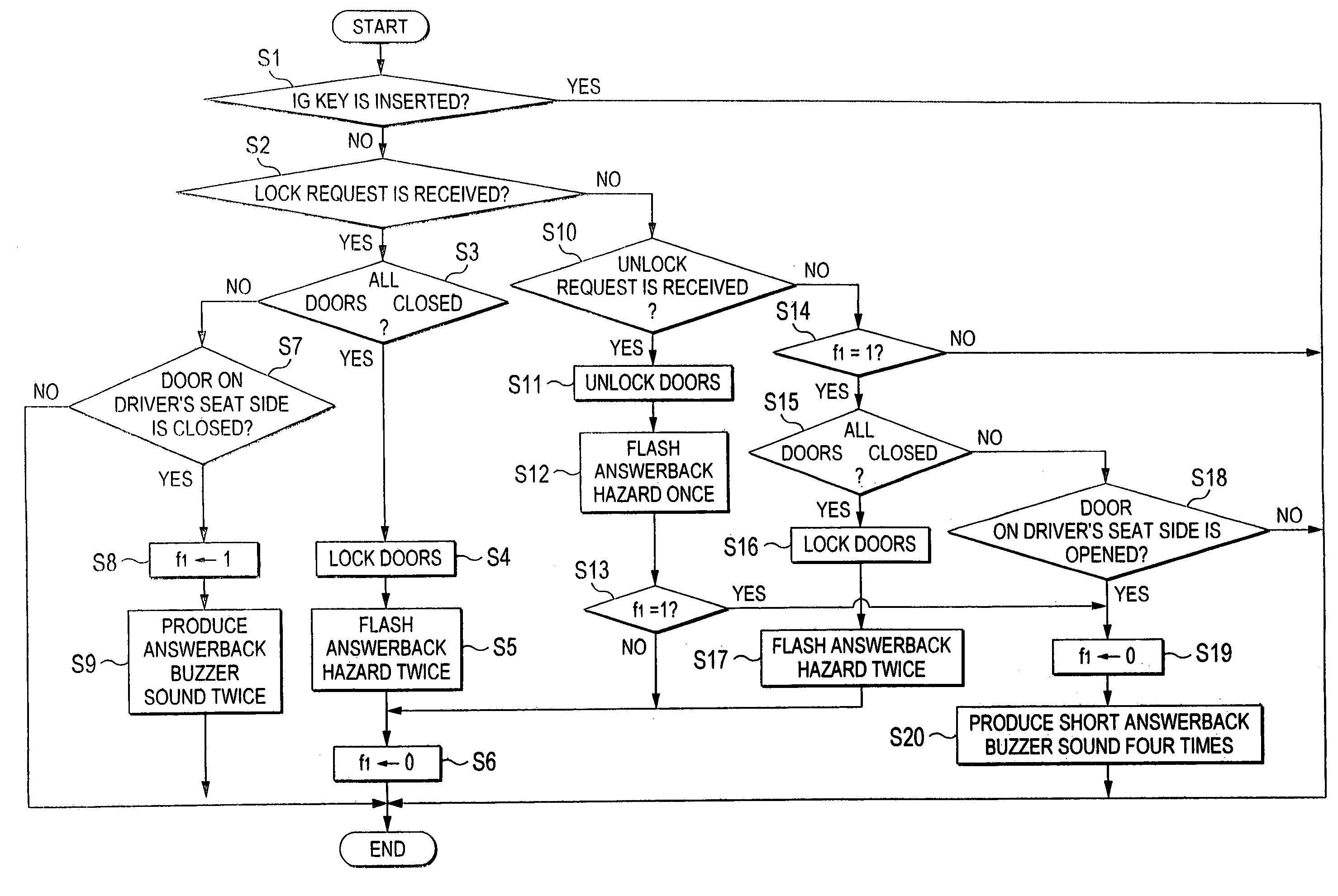
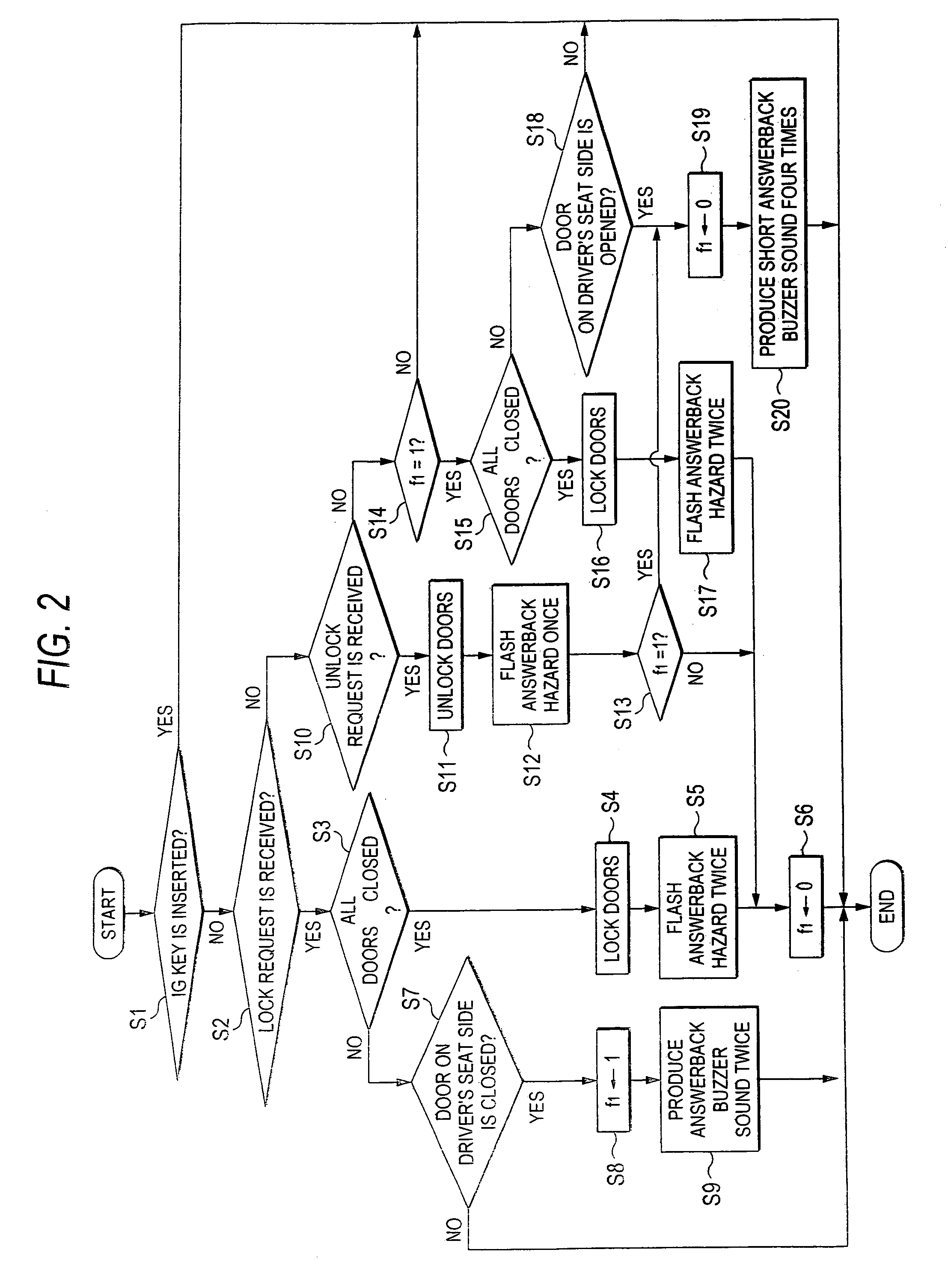
[0024]That is, the driver operates only the transmitter for transmitting a door lock request signal after closing the door on the driver's seat side, whereby the “automatic lock mode” is entered. Thus, if a fellow passenger exists, the need for the driver to wait until all doors of the vehicle are closed as with the vehicle door lock apparatus in the related art is eliminated, so that the inconvenience of operation can be eliminated.
[0028]That is, if the door on the driver's seat side is open, the “automatic lock mode” is not entered even if a door lock request is received. Thus, if the user'closes the door with the transmitter left in the cabin after operating the transmitter for transmitting a lock request signal with the door on the driver's seat side open, the door is not automatically locked. Accordingly, an accident of confining the transmitter in the cabin can be prevented from occurring.
[0030]That is, if any other door than the door on the driver's seat side, the driver operates only the transmitter for transmitting a door lock request signal after closing the door on the driver's seat side, whereby the “automatic lock mode” is entered. Thus, if a fellow passenger exists, the need for the driver to wait until all doors of the vehicle are closed as with the vehicle door lock apparatus in the related art is eliminated, so that the inconvenience of operation can be eliminated.
[0046]According to the described vehicle door lock apparatus of the sixth aspect, the user is informed that door locking in the “automatic lock mode” is complete, so that the user can easily check that door locking is complete.
[0060]Therefore, the “automatic lock mode” can be easily released as the user desires, so that an apparatus excellent in practicality can be provided. If the door on the driver's seat side is opened after the “automatic lock mode” is entered, a problem of confining the transmitter in the cabin occurs. However, if the door on the driver's seat side is opened, the “automatic lock mode” is forcibly released, whereby confining the transmitter in the cabin can be prevented.

Problems solved by technology

Thus, if a fellow passenger exists, the driver needs to check that all doors are closed before operating the transmitter; it is extremely irksome for the driver.
However, in the invention disclosed in official gazette 1, the transmitter and the vehicle-installed receiver need to be provided each with the transmission-reception circuit and there is a problem of complicating the configuration and increasing the costs.
However, the apparatus disclosed in official gazette 2 involves the risk of confining the transmitter in the cabin.

Method used


Image

  • Vehicle door lock apparatus
  • Vehicle door lock apparatus
  • Vehicle door lock apparatus

Examples


first embodiment

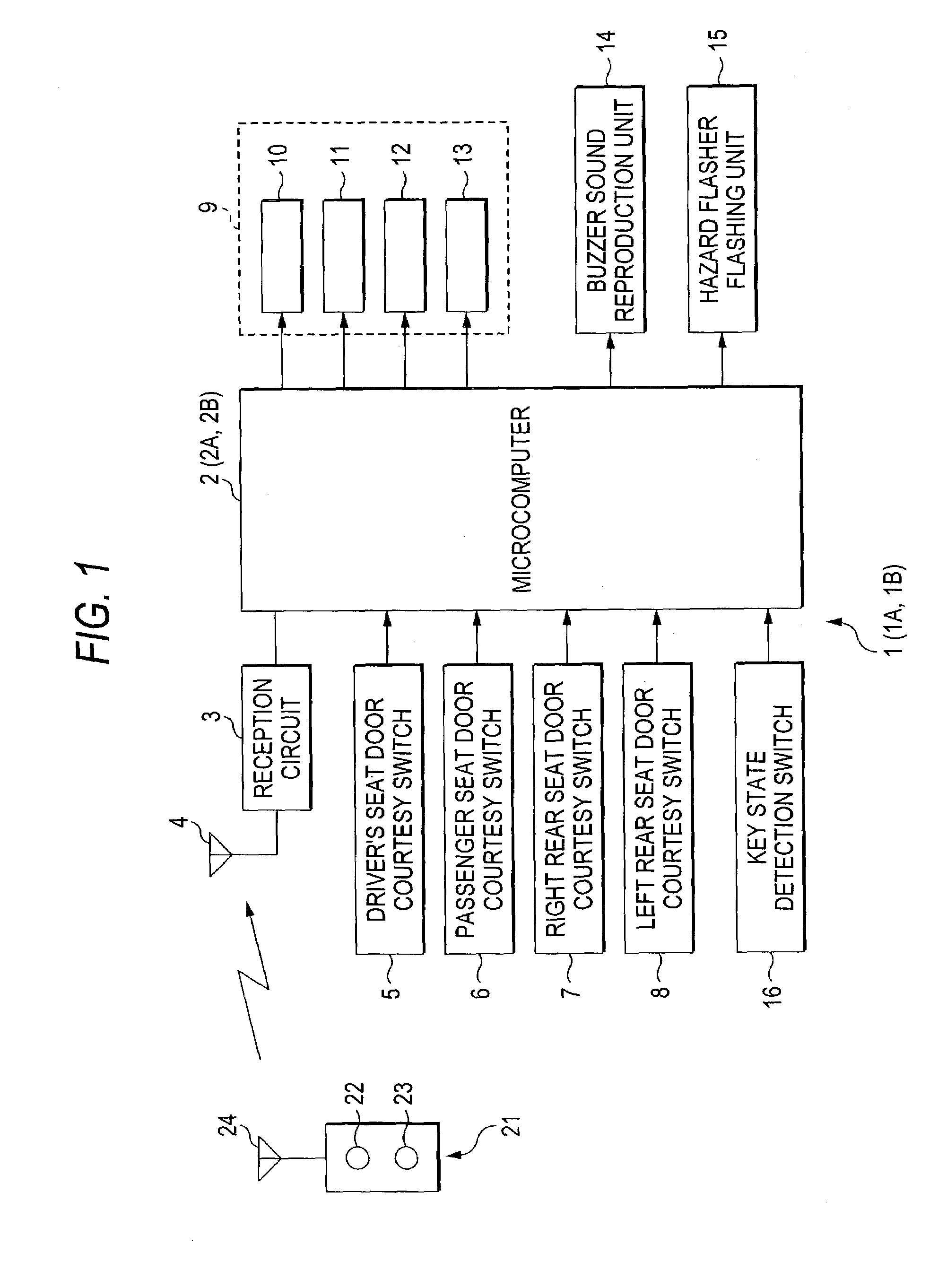
[0067]Referring now to the accompanying drawings, there are shown preferred embodiments of vehicle door lock apparatus according to the invention. FIG. 1 is a block diagram to schematically show the main part of a vehicle door lock apparatus according to the invention. In the figure, numeral 1 denotes a vehicle door lock apparatus. The vehicle door lock apparatus 1 has a microcomputer 2, a reception circuit 3, and an antenna 4, and the reception circuit 3 is connected to the microcomputer 2. The reception circuit 3 can receive a signal transmitted from a transmitter 21 (described later) through the antenna 4.

[0068]Connected to an input of the microcomputer 2 are door courtesy switches 5 to 8 for detecting the open / closed state of doors (a door on the driver's seat side, a door on the passenger seat side, a door on the right rear seat side, and a door on the left rear seat side) and a key state detection switch 16 for determining as to whether or not an ignition key is inserted into ...

second embodiment

[0086]Processing operation (2) performed by the microcomputer 2A in the vehicle door lock apparatus 1A according to the invention will be discussed with reference to a flowchart of FIG. 3. To begin with, whether or not an ignition key is inserted in a key cylinder is determined based on a signal detected by a key state detection switch 16 (step S21). If a door is locked when the ignition key is inserted in the key cylinder, there is a fear of confining the ignition key in the cabin. Thus, if it is determined that the ignition key is inserted in the key cylinder, the processing operation (2) is terminated.

[0087]On the other hand, if it is not determined at step S21 that the ignition key is inserted in the key cylinder, then whether or not a door lock request is received from a transmitter 21 is determined (step S22). If it is determined that a lock request is received, then whether all doors are closed is determined based on signals detected by door courtesy switches 5 to 8 (step S23...

third embodiment

[0101]Processing operation (3) performed by the microcomputer 2B in the vehicle door lock apparatus 1B according to the invention will be discussed with reference to flowcharts of FIGS. 4 and 5. To begin with, whether or not an ignition key is inserted in a key cylinder is determined based on a signal detected by a key state detection switch 16 (step S51). If a door is locked when the ignition key is inserted in the key cylinder, there is a fear of confining the ignition key in the cabin. Thus, if it is determined that the ignition key is inserted in the key cylinder, the processing operation (3) is terminated.

[0102]On the other hand, if it is not determined at step S51 that the ignition key is inserted in the key cylinder, then whether or not a door lock request is received from a transmitter 21 is determined (step S52). If it is determined that a lock request is received, then whether all doors are closed is determined based on signals detected by door courtesy switches 5 to 8 (st...


PUM


Abstract

A vehicle door lock apparatus receives a signal from a portable transmitter and at least locks a door based on the received signal. When a door lock request is received from the transmitter and the door on the driver's seat side is closed, signals detected by door courtesy switches are monitored. When all doors of the vehicle are closed, a door lock actuator is controlled for locking all doors by a lock unit.

Description

[0001]The present disclosure relates to the subject matter contained in Japanese Patent Application No.2001-289199 filed on Sep. 21, 2001, which is incorporated herein by reference in its entirety.BACKGROUND OF THE INVENTION[0002]1. Field of the Invention[0003]This invention relates to a vehicle door lock apparatus and more particularly to a vehicle door lock apparatus for locking and unlocking a door by remote operation.[0004]2. Description of the Related Art[0005]A vehicle door lock apparatus receives and interprets a signal transmitted from a small-sized transmitter excellent in portability and locks or unlocks a door. For example, upon reception of a lock request signal from the transmitter, the vehicle door lock apparatus places a door lock mechanism in a lock state; on the other hand, upon reception of an unlock request signal from the transmitter, the vehicle door lock apparatus places the door lock mechanism in an unlock state. Thus, the vehicle door lock apparatus enables t...

Claims


Application Information

Patent Timeline
IPC IPC(8): E05B65/20E05B49/00B60J5/00B60R25/01B60R25/10B60R25/34G07C9/00
CPCE05B77/48G07C9/00182G07C2009/00793Y10T70/65E05B49/00
Inventor SASAKI, YOSHIHIROYOSHIMURA, MINORU
Owner FUJITSU GENERAL LTD
Learn More