Apparatus and method for movement of electricity or fluid into and out of the body

Inactive Publication Date: 2005-11-17
SILVER THEODORE A +1
View PDF10 Cites 38 Cited by
  • Summary
  • Abstract
  • Description
  • Claims
  • Application Information

AI Technical Summary

Benefits of technology

[0014] It is a further object and feature of this invention to eliminate, substantially, the risk of infection associated with “cannulae,”“peripherally inserted central catheters,”“tunneled central venous catheters,”“indwelling catheters” and related devices now devoted to introducing electricity or fluid to the inside of the human body on long term bases.
[0015] It is a further object and feature of this invention to eliminate, substantially, the necessity for regular, repeated needle puncture associated with syringes, intravenous catheters, and related devices now used to facilitate regular, repeated injection of medication or other processes that require regular access to blood vessels or other spaces deep to the skin.
[0016] It is a further object and feature of this invention to provide a device that allows for the introduction of an ongoing supply of electricity needed and suited to the operation of prosthetic devices located inside the body/deep to the skin, without creating or maintaining an opening through the skin, and thus to substantially eliminate the serious and significant risk of infection now associated with such efforts.
[0017] It is a further object and feature of this invention to provide a device that allows for the movement of fluid between the outside of the body and a blood vessel(s) or other site(s) located anywhere deep to the skin, without opening the skin and thereby to (a) reduce or subst

Problems solved by technology

Unlike pacemakers, they require such electrical power as cannot be provided long term by a battery located within the body.
If the process is to be conducted over a long term the opening remains in place and presents a risk of serious infection.
Both tunneled central venous catheters and PICCs have infection as a chief cause of morbidity and mortality.
Prior art offers no such device.
Injection

Method used


Image

  • Apparatus and method for movement of electricity or fluid into and out of the body
  • Apparatus and method for movement of electricity or fluid into and out of the body
  • Apparatus and method for movement of electricity or fluid into and out of the body

Examples


Embodiment Construction

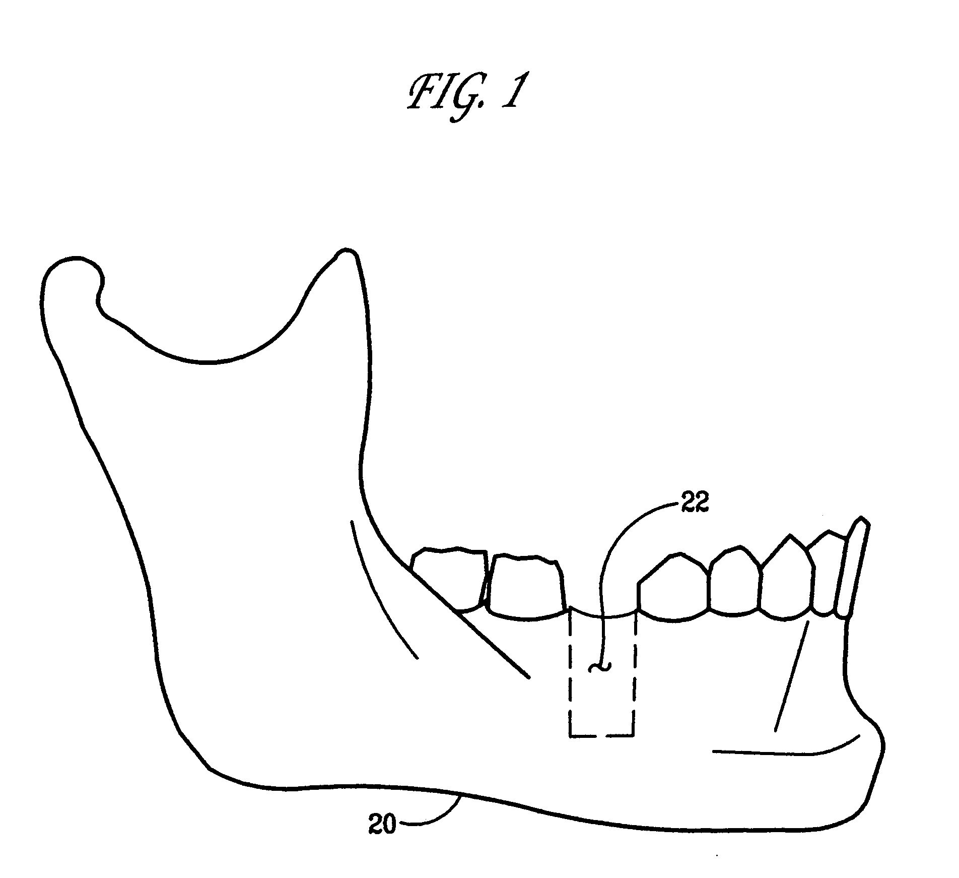
[0035] Referring to FIG. 1, a premolar / bicuspid or molar (or other) tooth has been removed from the mandible 20 (on right or left side). In the resulting space there is drilled downward through the mandible a vertically oriented tunnel 22, 10 mm to 15 mm deep and 4 mm to 7.5 mm in diameter (or of such other depth and diameter as suits the purpose described in the next sentence).

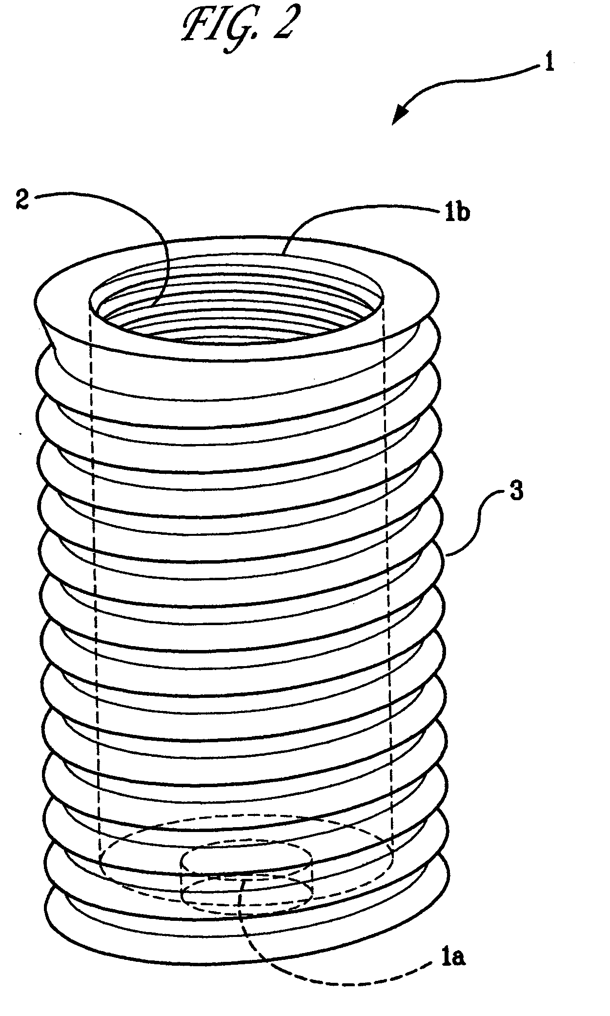
[0036] Referring to FIG. 2, driven into that tunnel, after the fashion of a screw, is a hollow entity or screw 1, roughly cylindrical in shape, open at both ends (the lower end 1A having a smaller diameter than the upper end 1B), composed of titanium, platinum or other non-reactive material. Its outer surface is threaded, as shown at 3 to facilitate fixture within the vertical tunnel 22 as shown in FIG. 3, with subsequent bone growth around it creating such a seal between sleeve and bone as does not permit the passage of microbes from the mouth or bodily exterior.

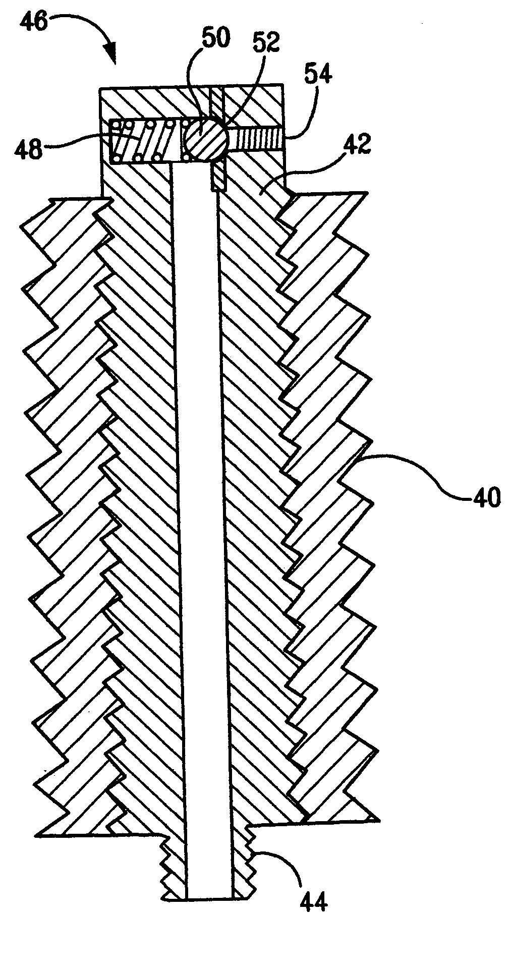
[0037] Referring to FIG. 4, the inner hollow...


PUM


Abstract

An apparatus for communication between a site within a body deep to the skin and a source, depot, reservoir, device, machine, or power source external to the body via the mouth of the body, comprising an implant for placement in tooth-supporting bone, the implant having a first portion extending into the mouth external to the tooth-supporting bone, a second portion for being embedded in the tooth-supporting bone, and an opening extending along the implant from the first portion to the second portion; and a conduit for coupling to the second portion of the implant when the implant is implanted in the tooth-supporting bone so that the conduit is in communication with the opening, the conduit being for extending from the implant to the site in the body.

Description

[0001] This application claims priority from provisional patent application Ser. No. 60 / 548,045 filed on Feb. 26, 2004, the entire contents of which are incorporated herein by reference.BACKGROUND OF THE INVENTION [0002] 1. Field of the Invention [0003] The present invention relates to apparatus and methods, for the movement of electricity or fluid into and out of the human body. More particularly, it is specifically directed to mediating such movement without traditional cannulae or catheters that pierce the skin and create significant risk of infection. [0004] 2. Background Art [0005] Movement of fluid into and / or out of the blood vessels or other spaces deep to the skin is a necessary incident to many therapies including, most commonly, the intravenous administration of medication and electrolytic fluid. Parenteral nutrition / hyperalimentation requires that fluid move into the vascular system from a reservoir outside the body. In the process of renal dialysis, fluid is removed fro...

Claims


Application Information

Patent Timeline
IPC IPC(8): A61C8/00A61C19/06A61M1/00A61N1/18
CPCA61C8/00A61C8/0022A61C19/063A61M2039/0282A61M39/0247A61M2039/025A61M2039/027A61M5/14276
Inventor SILVER, THEODORE A.WOOD, DAVID J.
Owner SILVER THEODORE A
Why Eureka
Try Eureka