Device for degassing and filtering plastic melts

A melting and degassing technology, which is applied in the field of extruding thermoplastic materials, can solve the problems of device pressure fluctuations, cannot guarantee the same quality of degassed and purified plastics, etc., and achieve the effect of improving the degassing effect

Active Publication Date: 2009-05-13
EREMA ENG RECYCLING MASCH & ANLAGEN GMBH
View PDF1 Cites 10 Cited by
  • Summary
  • Abstract
  • Description
  • Claims
  • Application Information

AI Technical Summary

Problems solved by technology

These vapors can be carriers of dirt, which enter the degassing section next to the filter and recontaminate the already filtered plastic, so that the same quality of the degassed and purified plastic cannot be guaranteed
In addition, pressure fluctuations in the device can occur due to excessive degassing, e.g. due to moisture in the plastic

Method used


Image

  • Device for degassing and filtering plastic melts

Examples


Embodiment Construction

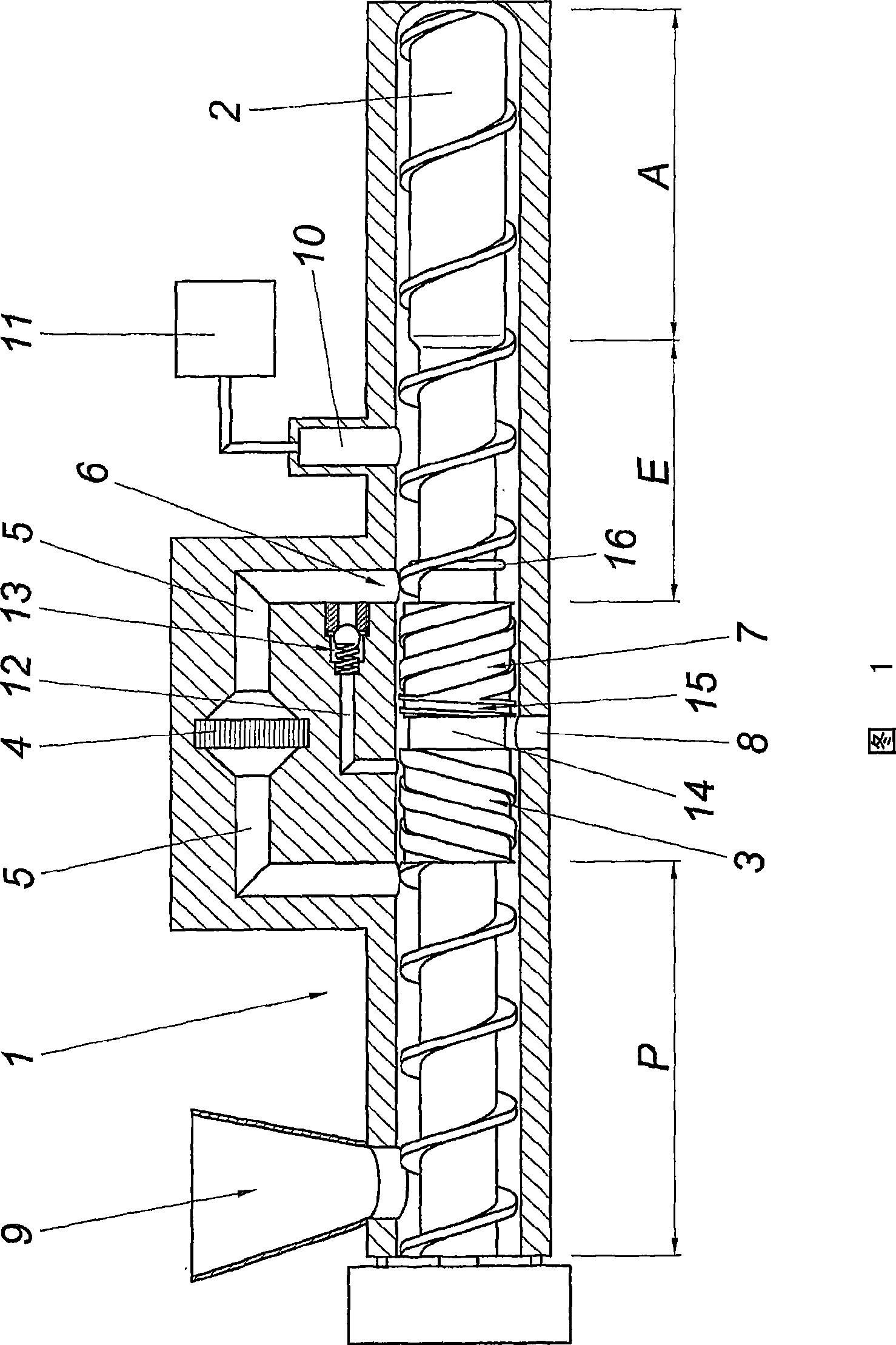
[0012] The device for extruding thermoplastic materials comprises an extrusion screw 2 mounted in a housing 1 , which has an inlet-side plasticizing section P and a degassing section E upstream of the outlet section A. Between the plasticizing section P and the degassing section E, a counter-conveying flight 3 and a flow channel 5 bridging the counter-conveying course 3 and containing a melt filter 4 are provided. In order to prevent the gas generated in the plasticizing section from overflowing directly into the degassing section, the extrusion screw 2 is formed in the same direction between the reverse conveying screw 3 and the outlet 6 in the degassing section E on the discharge side of the flow channel 5 The conveying screw 7, and the shell 1 is provided with a degassing hole 8 in the transitional part between the reverse and the same direction conveying screw 3, 7, through which the gas and dirt squeezed into the conveying screw part from the device 1 The medium is advant...


PUM


Abstract

The invention relates to a device for the extrusion of thermoplastic synthetic material featuring an extruder screw (2) which is mounted on a housing (1) comprising a plasticizing section (P) at the inlet side, a degassing section which is mounted upstream on a discharge section (A) and a conveying outlet (3) running in the opposite direction which is located between the plasticizing section (P) and the degassing section (E), with a flow channel (5) that contains a melt filter (4) which is bridged over by at least one of the conveying outlets (3) in the opposite direction. In order to create favorable production conditions, it is suggested that the extruder screw (2) forms a similar conveying outlet (7) running in the same direction between the conveying outlet (3) in the opposite direction and the downstream port (6) of the flow channel (5), and that the housing (1) has at least one degassing vent (8) at the transition area of the conveying outlet (3) running in the opposite direction and the conveying outlet (7) running in the same direction.

Description

technical field [0001] The invention relates to a device for extruding thermoplastic materials, with an extrusion screw supported in a housing, which comprises a plasticizing section on the input side, a degassing section preceding the discharge section, and a degassing section between the plasticizing section and the degassing section. The reverse feed flight between the gas sections also has at least one flow channel which bridges the reverse feed flight and contains a melt filter. Background technique [0002] Plastics, especially waste plastics, must be degassed or cleaned before further processing, so that the plastics are properly degassed and processed. When processing plastic from production waste or plastic material already in circulation, the need arises due to pressurization, painting or soiling to decontaminate this plastic before re-use. For this purpose (WO 93 / 04841 A1) it is known (WO 93 / 04841 A1) to melt the plastic material to be processed in an extruder, p...

Claims


Application Information

Patent Timeline
Patent Type & Authority Applications(China)
IPC IPC(8): B29C47/60B29C47/68B29C47/76B29C48/03B29C48/55B29C48/69B29C48/693B29C48/74B29C48/76
CPCB29C47/0009B29C47/0825B29C47/74B29C47/686B29C47/0871B29C47/767B29C47/68B29C47/6037B29C48/03B29C48/2564B29C48/268B29C48/55B29C48/69B29C48/693B29C48/74B29C48/767B29B7/845B29B7/58B29B7/429
Inventor H·舒尔茨
Owner EREMA ENG RECYCLING MASCH & ANLAGEN GMBH
Why Eureka
Try Eureka