
Grinding mechanism applicable to both external grinder roll module and end face grinding wheel module

A grinding mechanism and cylindrical grinding technology, applied in machine tools suitable for grinding the plane of the workpiece, machine tools designed for grinding the rotating surface of the workpiece, grinding machines, etc. Effect

Active Publication Date: 2009-06-03
HANGZHOU XIANGSHENG ABRASIVE MACHINE MFG
View PDF1 Cites 4 Cited by
  • Summary
  • Abstract
  • Description
  • Claims
  • Application Information

AI Technical Summary

Problems solved by technology

Its disadvantage: the two modules cannot be interchanged in the same institution

Method used


Image

  • Grinding mechanism applicable to both external grinder roll module and end face grinding wheel module
  • Grinding mechanism applicable to both external grinder roll module and end face grinding wheel module

Examples


Embodiment 1

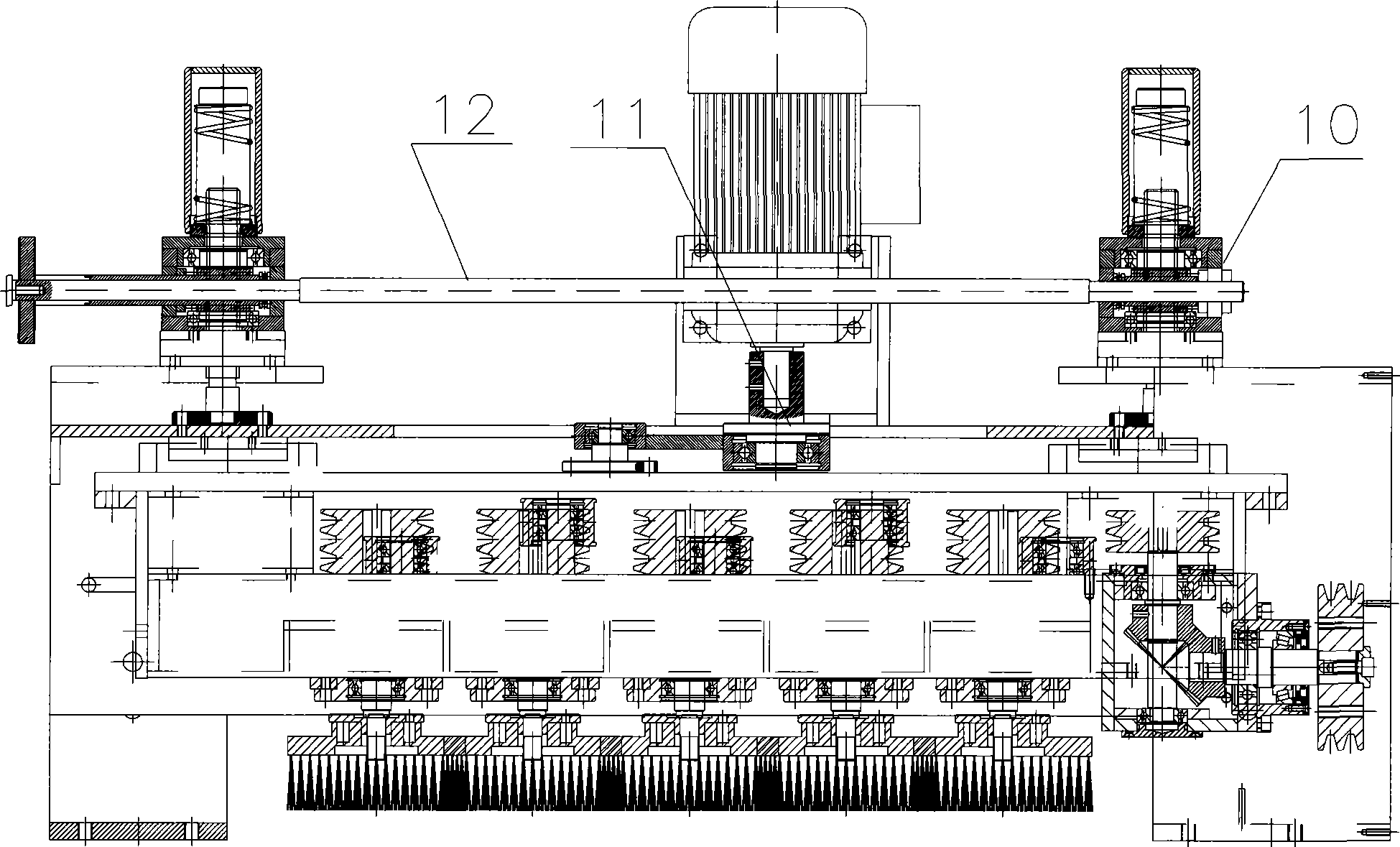
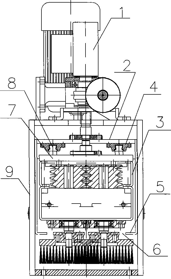
[0010] Embodiment 1: with reference to attached figure 1 and 2 . A universal grinding mechanism for cylindrical grinding roller modules and end surface grinding wheel modules. The worm gear mechanism 10 in the grinding mechanism is located on the upper end of the support 9 and is driven by the motor 1. The lifting mold frame 2 is located in the support 9 and on both sides of the lifting mold frame 2. It is in precise sliding fit with the inner wall of the bracket 9, driven by the worm gear mechanism 10 to rise or fall, and the worm gear box on the upper end surface of the bracket 9 adopts a rigid connecting rod 12 to act synchronously. The frame bottom of the lifting mold frame 2 is an open slide rail structure 6 , that is to say, the horizontal edges on both sides of the opening are slide rails 5 . The upper end surface of the transition plate 7 is provided with (several pieces) slide blocks 8 in parallel and is plugged and suspended with the (four sets) linear guide rails ...

Embodiment 2

[0011] Embodiment 2: On the basis of Embodiment 1, a method for working and exchanging the universal grinding mechanism of the cylindrical grinding roller module and the end face grinding wheel module, the worm gear mechanism 10 in the grinding mechanism is driven by a motor, and the lifting mold frame 2 is driven by The worm gear mechanism 10 drives it up or down, and the eccentric mechanism drives the transition plate 7 connected with the movement mechanism 3 to move left and right along the linear guide rail, thereby driving the movement mechanism 3 to move left and right; the outer cylindrical grinding roller module or the end face grinding wheel module is replaced When removing the power belt on the rear side and the four front and rear connecting screws, the outer cylindrical grinding roller module or end grinding wheel module can fall onto the slide rail at the bottom of the lifting mold frame, and the outer cylindrical grinding roller module or end grinding wheel module ...


PUM


Abstract

The invention relates to a grinding mechanism applicable to both an external grinder roll module and an end face grinding wheel module, wherein, in the grinding mechanism, an external grinder roll and an end face grinding wheel of a sander can be replaced conveniently in one mechanism. A worm gear of the grinding mechanism is positioned at the upper end of a bracket and driven by a motor; a lift bolster is positioned in the bracket and driven to ascend or descend by the worm gear; and an approach slab connected with a shift mechanism in a sliding manner is connected with an eccentric axle in an eccentric mechanism and driven by the eccentric mechanism to shift leftwards and rightwards. The invention has the advantages that the ascending or descending of the two modules is realized, the leftward and rightward shift of the two modules is realized, the shift frequency and the shift amplitude are both adjustable, and fast mutual replacement of the two modules in one mechanism is realized.

Description

technical field [0001] The invention relates to a grinding mechanism common to the outer cylindrical grinding roller module and the end grinding wheel module of a sanding machine, which can be easily replaced in the same mechanism, and belongs to the field of sander component assembly manufacturing. Background technique [0002] The patent number of the applicant is 200510117568.2, the title is "Combined Sanding Head and Combination Method of Sanding Head Mode". It is composed of a tension roller, a grinding plate, a second moving plate, a second fixed plate, a second rotary shaft and a second crankshaft. The sanding roller is located under the sanding head, and the driven roller and sanding roller are located side by side on the second moving plate. On the top, the grinding plate is located between the driven roller and the sanding roller and is connected to the lower end of the second moving plate, and the second fixed plate is connected to the second moving plate through ...

Claims


Application Information

Patent Timeline
Patent Type & Authority Applications(China)
IPC IPC(8): B24B27/00B24B5/37B24B7/16
Inventor 陈勇奇
Owner HANGZHOU XIANGSHENG ABRASIVE MACHINE MFG
Learn More