Hinge device for cellular phone

A cellular phone and hinged technology, applied in the field of hinged devices, can solve the problems of limited reduction in thickness, limited slimness of portable wireless terminals, and frictional noise generated by shells and springs, etc.

Inactive Publication Date: 2009-06-03
德铃电子株式会社
0 Cites 1 Cited by

AI-Extracted Technical Summary

Problems solved by technology

[0007] However, the above-mentioned prior art hinge device is limited in achieving a reduction in thickness because it requires a housing for accommodating the spring and the guide bar.
Therefore, portable wireless terminals us...

Abstract

The present invention discloses a hinge device for a cellular phone, which has no device housing and thus, can achieve a greater slimness of the cellular phone and reduce the generation of a noise during a sliding operation of a slide body included in the cellular phone. The hinge device includes a first push rod connected to a main body of the cellular phone and having a pin and a pin hole, and a second push rod connected to a slide body of the cellular phone and having a pin and a pin hole. The pin of the first push rod is penetrated through the pin hole of the second push rod, and the pin of the second push rod is penetrated through the pin hole of the first push rod. A spring is provided around each pin.

Application Domain

Substation equipmentTransmission

Technology Topic

Biomedical engineeringTelephony

Image

  • Hinge device for cellular phone
  • Hinge device for cellular phone
  • Hinge device for cellular phone

Examples

  • Experimental program(1)

Example Embodiment

[0023] Exemplary embodiments of the present invention will now be described in detail with reference to the accompanying drawings.
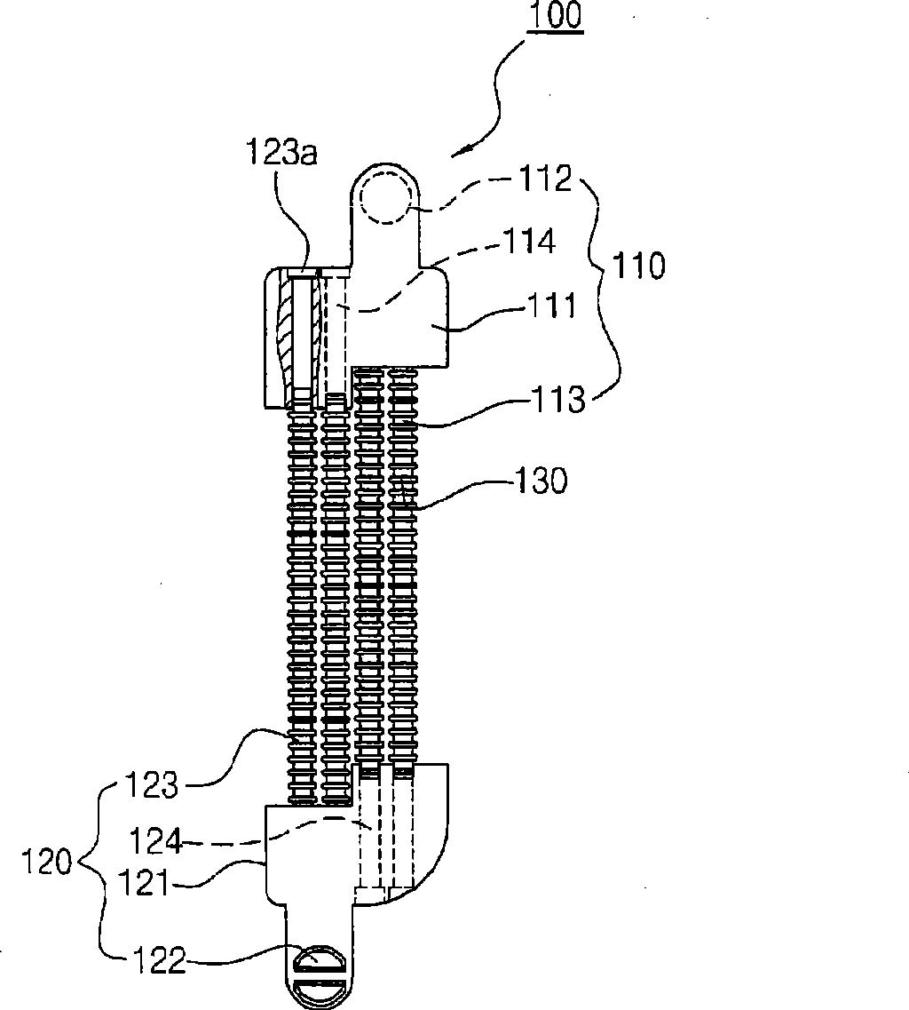
[0024] figure 2 It is a view illustrating the hinge device 100 according to the first embodiment of the present invention. Reference figure 2 , The hinge device 100 for a cellular phone according to the present invention includes a pair of push rods 110 and 120, and a spring 130.
[0025] From the fact that the pair of push rods 110 and 120 have the same configuration as each other: each push rod 110 or 120 includes a body 111 or 121, a plurality of bolts 113 or 123, and a bolt hole 114 or 124. The difference between the push rods 110 and 120 is that any one of these push rods is the first push rod 110 having the connection portion 112 to be connected to the main body (not shown) of the cellular phone, and the other push rod The rod is a second push rod 120 having a connecting portion 122 to be connected to a sliding body (not shown) of the cellular phone.
[0026] Considering the connection structure of the first push rod 110 and the second push rod 120, the first push rod 110 and the second push rod 120 are arranged to face each other, and the plug 113 formed on the first push rod 110 penetrates into the first push rod 110. The pin hole 124 in the second push rod 120. Similarly, the plug pin 123 formed in the second push rod 120 penetrates the plug hole 114 formed in the first push rod 110.
[0027] Although the latch pins 113 and 123 are installed at the first and second push rods 110 and 120 to penetrate the latch holes 124 and 114, in order to prevent the latch pins 113 and 123 from being completely separated from the latch holes 124 and 114, each of the latch pins 113 and 123 A stopper 123a is formed at its end. The stopper 123a may have any shape or size, as long as the stopper 123a cannot pass through the associated pin hole 114 or 124. In this case, the latch hole 114 or 124 may be formed with a stepped portion at its end corresponding to the stopper 123a to prevent the stopper 123a from passing through the latch hole 114 or 124.
[0028] The spring 130 is interposed between the first push rod 110 and the second push rod 120. In particular, the spring 130 is preferably arranged around the corresponding pins 113 and 123.
[0029] Figures 3-7 illustrate a hinge device 200 according to a second embodiment of the invention.
[0030] 3 and 4, the hinge device 200 of this embodiment includes a first push rod 210, a second push rod 220, guide parts 216 and 226 formed on the corresponding push rods 210 and 220, and penetrate the corresponding guide parts 216 and 226 of the guide bars 225 and 215. Specifically, the guide bar 215 of the first push rod 210 penetrates the guide part 226 of the second push rod 220, and the guide bar 225 of the second push rod 220 penetrates the guide part 216 of the first push rod 210. Of course, in order to prevent the guide bars 215 and 225 from being completely separated from the guide parts 226 and 216, each of the guide bars 215 and 225 is formed with a stopper 215a at its end, and each of the guide parts 216 and 226 is It is formed with a stepped portion 226b. The reason why the guide bars 215 and 225 and the guide portions 216 and 226 are configured to have the above configuration is to prevent the first push rod 210 and the second push rod 220 from being completely separated from each other, while allowing the first and second push rods 210 and 220 to move. Leaving or moving towards each other. That is, the functions of the guide bars 215 and 225 and the guide portions 216 and 226 are the same as those of the stopper 123a and the bolt hole formed at the end of the bolt included in the hinge device 100 of the aforementioned first embodiment.
[0031] Except for the above description, the other configuration of the hinge device 200 of the second embodiment is the same as the configuration of the hinge device 100 of the aforementioned first embodiment. That is, each push rod 210 or 220 is arranged such that its body 211 or 221 has a pin 213 or 223 and a pin hole 214 or 224. In addition, the two push rods 210 and 220 are arranged to face each other so that the pin 213 or 223 of any one of these push rods penetrates the pin hole 224 or 214 of the other push rod. The spring 230 is placed between the two push rods 210 and 220.
[0032] Since the hinge device 200 of the second embodiment includes the guide bars 215 and 225 and the guide portions 216 and 226, there is no need to provide a stopper 123a at the end of each pin as described in the aforementioned first embodiment .
[0033] In the following, we will refer to Figure 5-7 The operation of the hinge device according to the second embodiment of the present invention is described.
[0034] Such as Figure 5 As shown, one side of the first push rod 210 is connected to the main body MB of the cellular phone, and one side of the second push rod 220 is connected to the sliding body SB of the cellular phone.
[0035] If the sliding body SB moves down after receiving an external force, such as Figure 6 As shown, the bolts move, and as a result, they further penetrate the bolt holes, thereby allowing the first push rod 210 and the second push rod 220 to approach each other. In this case, the spring 230 installed around the corresponding plug is compressed by the first and second push rods 210 and 220.
[0036] Then, if the sliding body SB moves further down after receiving an external force, such as Figure 7As shown, the compressed spring 230 is resiliently restored, thereby acting to push the first push rod 210 and the second push rod 220 in opposite directions. With the elastic restoring force of the spring 230, even if the external force is no longer applied to the sliding body SB, the subsequent downward movement of the sliding body SB can be realized naturally.
[0037] Although the exemplary embodiments of the present invention have been disclosed for illustrative purposes, those skilled in the art will appreciate that various changes can be made without departing from the scope and spirit of the present invention as disclosed in the drawings. Add and replace.
[0038] Industrial applicability
[0039] As is obvious from the above description, the present invention provides a hinged device for a cellular phone, which does not require a separate device housing, thereby achieving a greater degree of slimming of the cellular phone and reducing the amount contained in the cellular phone. Noise is generated during the sliding operation of the sliding body in the phone.

PUM

no PUM

Description & Claims & Application Information

We can also present the details of the Description, Claims and Application information to help users get a comprehensive understanding of the technical details of the patent, such as background art, summary of invention, brief description of drawings, description of embodiments, and other original content. On the other hand, users can also determine the specific scope of protection of the technology through the list of claims; as well as understand the changes in the life cycle of the technology with the presentation of the patent timeline. Login to view more.
Why Eureka
Try Eureka