Door lock bolt structure

A latch and structure technology, applied in the latch field of door locks, can solve the problems of reduced anti-theft performance of door locks, inconvenience, shrinking into the housing, etc., and achieve the effect of improving anti-theft performance

Active Publication Date: 2009-06-17
TAIWAN FU HSING INDAL +1
View PDF0 Cites 2 Cited by
  • Summary
  • Abstract
  • Description
  • Claims
  • Application Information

AI Technical Summary

Problems solved by technology

[0002] When the bolt of the existing door lock is locked, the bolt will be snapped into the hole of the door frame to maintain the locked state. However, when the bolt is deliberately opened by a thief or a destructive object, the existing bolt is very easy to open. It is pulled and retracted into the housing to cause unbolting, which greatly reduces the anti-theft performance of the door lock. In addition, before installing the lock bolt on the general door panel, a suitable lock is usually selected according to the opening direction of the door panel (such as left-handed door or right-handed door). Latch, the main reason is that the existing latches are not suitable for both left-handed and right-handed doors in design, therefore, if the left-handed door must be left-handed, the left-handed door must be selected, otherwise, the right-handed door must be selected, but , once the lock bolt is selected incorrectly or the opening direction of the door panel is reversed due to the change of the space design, the original lock bolt will not be used, and a suitable lock bolt must be purchased again. In this way, additional replacement costs will be incurred. In addition, the existing latch cannot be used for both left-handed and right-handed doors, which will cause great trouble and inconvenience in installation.
[0003] This shows that the latch bolt of above-mentioned existing door lock obviously still has inconvenience and defect in structure and use, and urgently needs to be further improved
In order to solve the above-mentioned problems, the relevant manufacturers have tried their best to find a solution, but for a long time no suitable design has been developed, and the general product has no suitable structure to solve the above-mentioned problems. This is obviously the relevant industry. Urgent problem

Method used


Image

  • Door lock bolt structure
  • Door lock bolt structure
  • Door lock bolt structure

Examples


Embodiment Construction

[0073] In order to further explain the technical means and effects that the present invention takes to achieve the intended purpose of the invention, below in conjunction with the accompanying drawings and preferred embodiments, the specific implementation, structure, characteristics and details of the latch structure of the door lock proposed according to the present invention will be described below. Its effect is described in detail below.

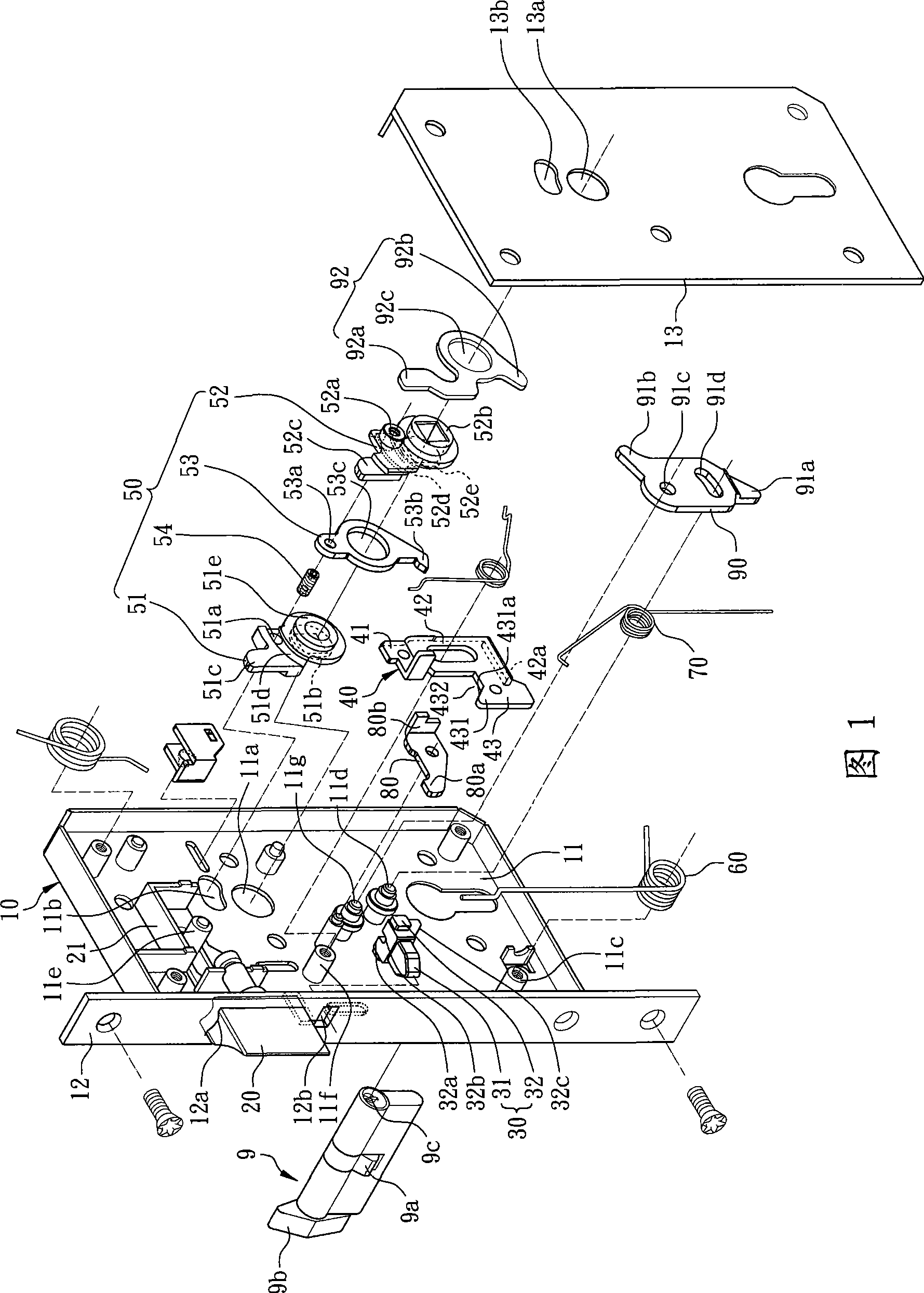
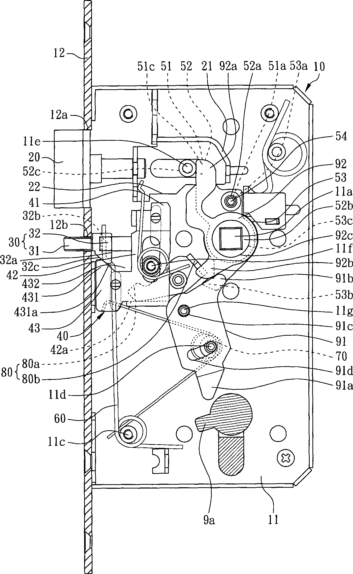
[0074] Please refer to Figure 1 and figure 2 , which is a preferred embodiment of the present invention, a latch structure of a door lock includes a housing 10, a latch 20, an anti-theft component 30, a sliding plate 40, an unlatching assembly 50, a first The elastic member 60, a second elastic member 70 and a toggle plate 80, the housing 10 has a base 11, a side plate 12 formed at one end of the base 11 and a cover plate 13 opposite to the base 11 The base 11 is formed with a first through hole 11a and a first opening 11b. In addition...


PUM


Abstract

The invention relates to a plunger latch of a door lock, comprising a case, a lock plunger, an anti-theft piece and a sliding panel, wherein, the case is provided with a base and a lateral plate formed at one end of the baseplate, the lateral plate is provided with a lock plunger hole and a through hole arranged opposite to the lock plunger hole, the lock plunger is arranged in the lock plunger hole of the lateral plate in an elastic manner, the anti-theft piece is arranged in the through hole of the lateral plate in an elastic manner, the sliding panel is provided with a block part, a propping part and a pin joint part which connects the block part and the propping part, wherein, the block part is corresponding to the lock plunger and can block the lock plunger, the pin joint part is pivoted on the base of the case, while the anti-theft piece can limit the propping part. When the door is close, the anti-theft piece of the invention retracts into the shell and stops limits on the propping part of the sliding panel, meanwhile, the block part of the sliding panel shifts and blocks the lock plunger, so as to prevent the lock plunger from retracting into the case for unlatching.

Description

technical field [0001] The invention relates to a lock bolt of a door lock, in particular to a lock bolt structure of a door lock which utilizes an anti-theft piece and a sliding plate to improve the anti-theft performance. Background technique [0002] When the bolt of the existing door lock is locked, the bolt will be snapped into the hole of the door frame to maintain the locked state. However, when the bolt is deliberately opened by a thief or a destructive object, the existing bolt is very easy to open. It is pulled and retracted into the housing to cause unbolting, which greatly reduces the anti-theft performance of the door lock. In addition, before installing the lock bolt on the general door panel, a suitable lock is usually selected according to the opening direction of the door panel (such as left-handed door or right-handed door). The main reason is that the existing latches are not suitable for both left-opening and right-opening doors in design. Therefore, if t...

Claims


Application Information

Patent Timeline
IPC IPC(8): E05B63/20E05B15/12
Inventor 黄莲溪蒋光浚
Owner TAIWAN FU HSING INDAL
Why Eureka
Try Eureka