Lock

Inactive Publication Date: 2008-01-17
CHEN RICK TEYU
View PDF13 Cites 13 Cited by
  • Summary
  • Abstract
  • Description
  • Claims
  • Application Information

AI Technical Summary

Benefits of technology

[0019]By such an arrangement, a user may replace some of the elements to modify the lock for the purposes of selective use with a thumb-piece type outer handle or a rotational outer handle. The cost for converting a lock for use with a thumb-piece type outer handle into a lock for use with a rotational outer handle is largely reduced.
[0020]Preferably, the lock further comprises an outer handle control device including a locking member extendible through the faceplate, the locking member having a stop, a

Problems solved by technology

However, such a door lock can only be

Method used


Image

  • Lock
  • Lock
  • Lock

Examples


Example

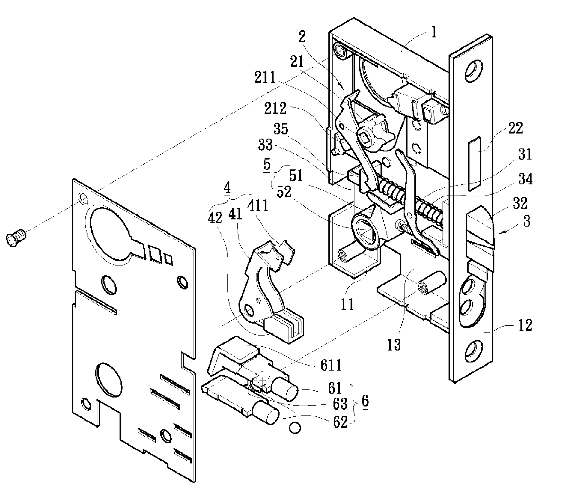
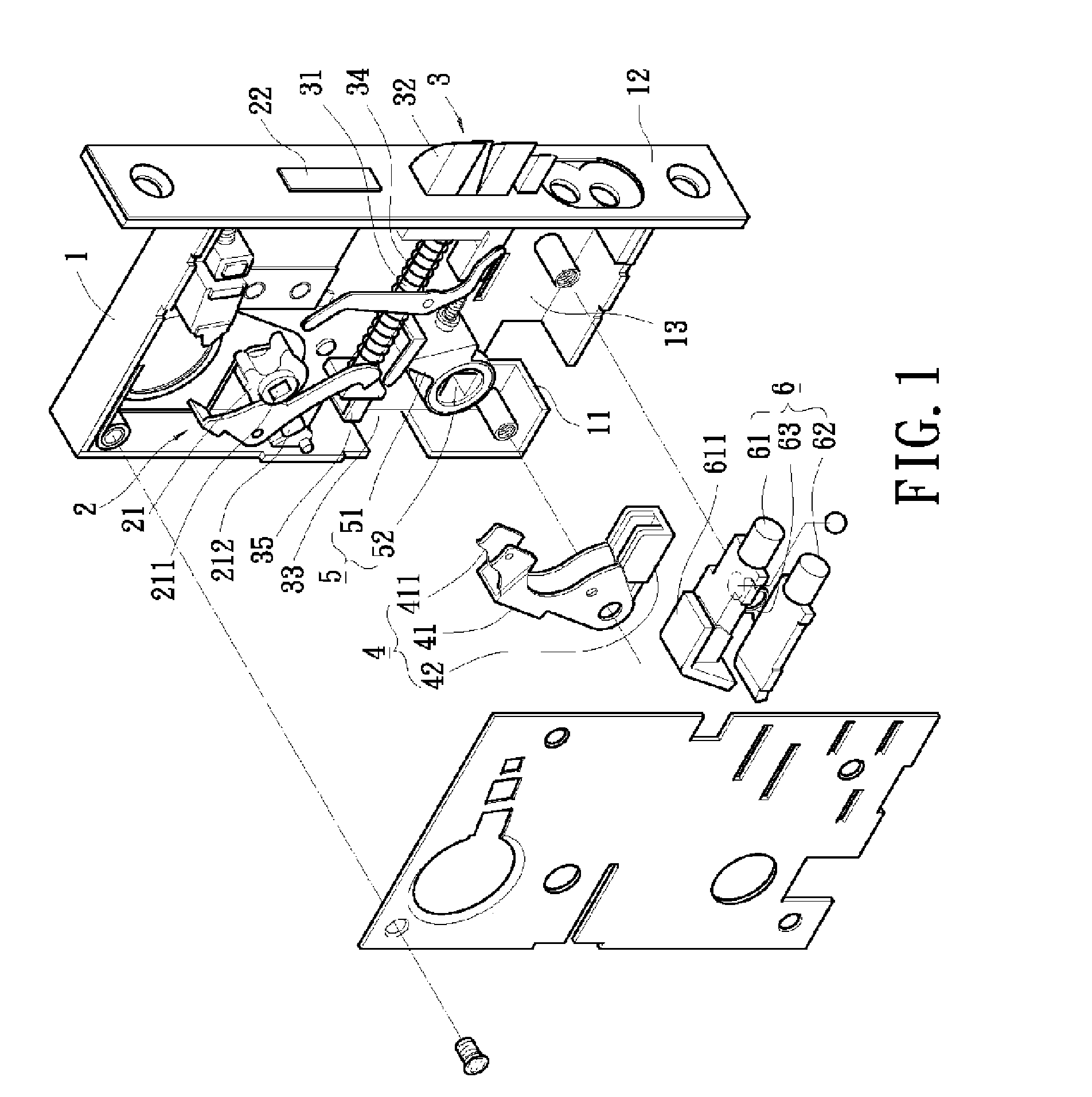
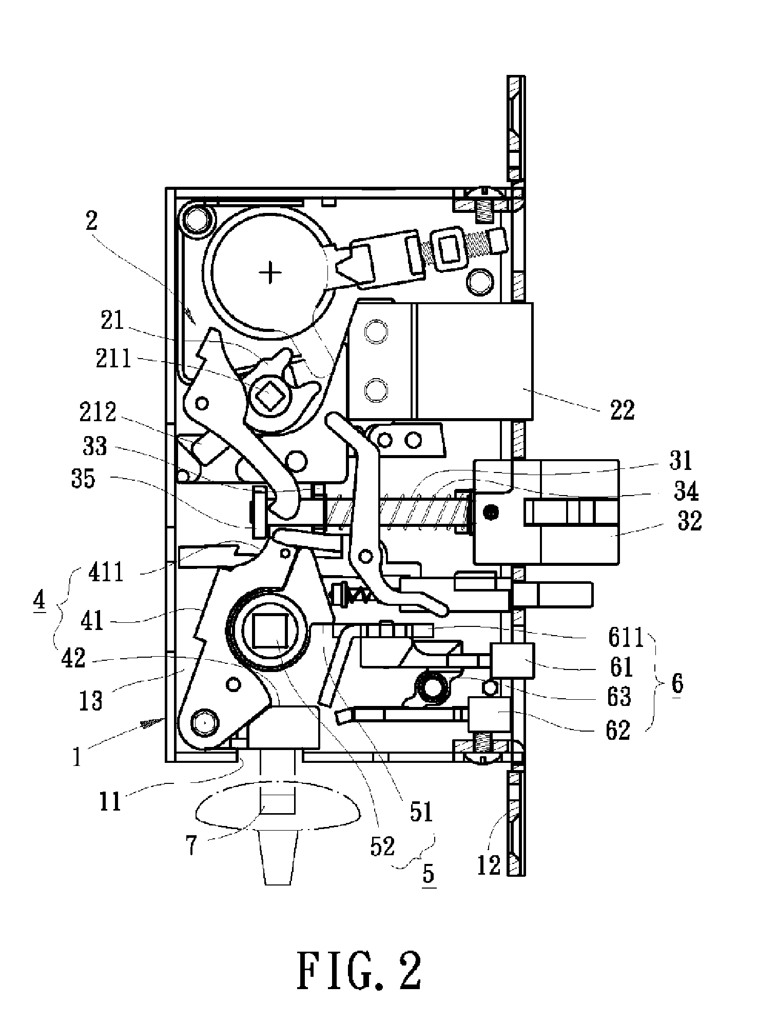
[0034]FIGS. 1 and 2 illustrate an example of a lock in accordance with the present invention for use with a thumb-piece type outer handle. The lock comprises a case 1, a bolt-driving mechanism 2, a bolt assembly 3, an actuating device 4, a pivotal seat 5, and an outer handle control device 6. The case 1 receives all of the elements and includes a slot 11 in an end face of the case 1, a faceplate 12 adjacent to the end face having the slot 11, and a mounting wall 13 adjacent to the faceplate 12.

[0035]Still referring to FIGS. 1 and 2, the bolt-driving mechanism 2 includes a driving member 21 and an auxiliary bolt. The driving member 21 is rotatably mounted to the mounting wall 13 and includes an insertion hole 211 and a push rod 212. A turn-piece (not shown) or the like is coupled with the insertion hole 211 and may be turned for turning the driving member 21. The auxiliary bolt 22 is extendible through the faceplate 12 and connected to the driving member 21. Thus, when the driving me...


PUM


Abstract

A lock includes a case, an actuating device for retracting a latch bolt, and a first and second pivotal assembly selectively coupled to a mounting wall of the case. The first pivotal assembly includes a first pivotal seat for coupling with a rotational outer handle and a second pivotal seat for coupling with an inner handle. The second pivotal assembly includes a third pivotal seat for coupling with an inner handle. One of the first pivotal assembly and the second pivotal assembly is selected for use with one of the rotational outer handle and a thumb-piece type outer handle. A rotational pressing member is selectively and rotatably mounted to the mounting wall when the lock is used with the thumb-piece type outer handle. The rotational pressing member is actuated to turn the actuating device for retracting the latch bolt when the thumb-piece type outer handle is pressed.

Description

BACKGROUND OF THE INVENTION[0001]1. Field of the Invention[0002]The present invention relates to a lock. More particularly, the present invention relates to a lock for selective use with a rotational outer handle or a thumb-piece type outer handle.[0003]2. Description of Related Art[0004]Taiwan Patent Publication No. M281045 discloses a general-purpose door lock comprising a case, a bolt-driving mechanism, a bolt assembly, a pivotal seat, an actuating rod, and an outer handle control device. The case receives all elements of the door lock. The bolt-driving mechanism controls movement of an auxiliary bolt. The bolt assembly is mounted in an intermediate section of the door lock and includes a latch bolt extending through a side of the case. The pivotal seat includes a through-hole through which an outer handle is extended. The pivotal seat includes a push member and a catch. An end of the actuating rod is engaged with the bolt assembly. The push member presses against the actuating r...

Claims


Application Information

Patent Timeline
IPC IPC(8): E05B59/00E05B63/14
CPCE05B13/004E05B63/16E05B59/00Y10T70/5226
Inventor CHEN, RICK-TEYU
Owner CHEN RICK TEYU
Why Eureka
Try Eureka