
Railway track-mounted machinery

A technology of railway tracks and machinery, applied in the direction of wheel axle self-adjustment, etc., can solve the problems of car body deflection, difficulty in standing for construction personnel, and instability of workpiece placement, and achieve the effect of eliminating car body deflection.

Inactive Publication Date: 2009-07-15
GEMAC ENG MACHINERY
View PDF0 Cites 9 Cited by
  • Summary
  • Abstract
  • Description
  • Claims
  • Application Information

AI Technical Summary

Problems solved by technology

[0002] When the current railway track machinery is working in a curved section, because the rails on the outside of the line are higher than the rails on the inside (railway term: outer rail superelevation), the car body is deflected, making it difficult for construction workers to stand and the workpiece to be placed unstable.

Method used


Image

  • Railway track-mounted machinery
  • Railway track-mounted machinery
  • Railway track-mounted machinery

Examples


Embodiment Construction

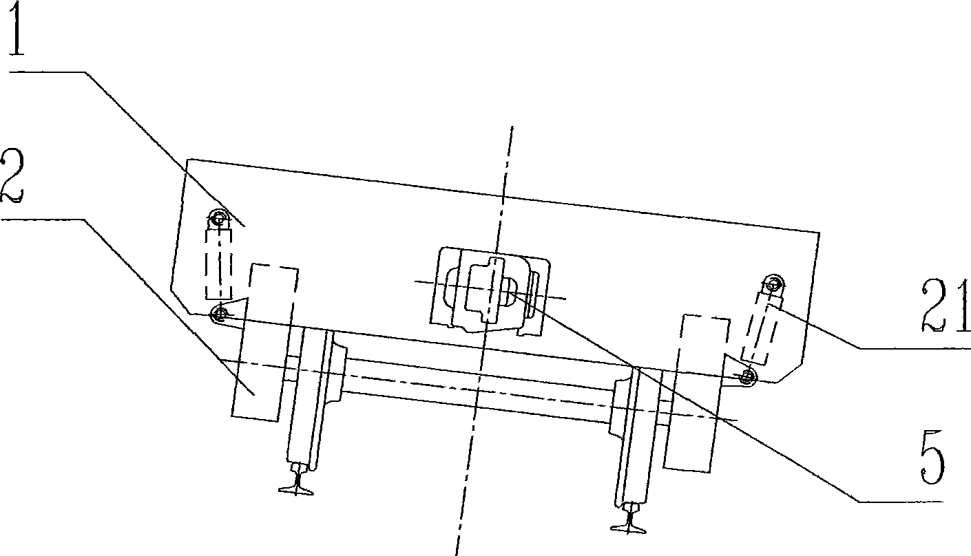
[0022] figure 1 Among them, (1) is the main frame, (2) is the bogie, (21) is the leveling mechanism, and (5) is the coupler. Now the main frame (1) remains on the inclined position together with the bogie (2), and the vehicle coupler (5) also remains on the inclined position.

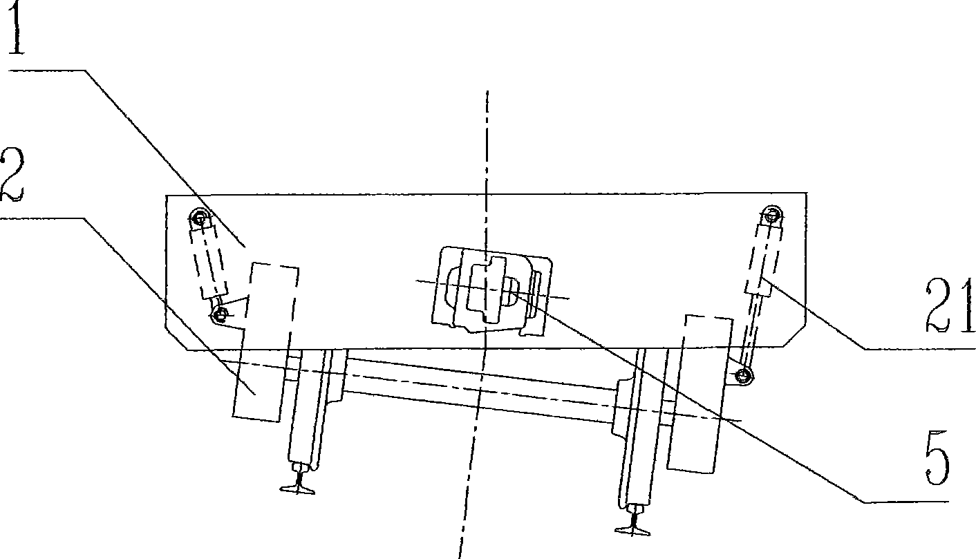
[0023] figure 2 At this time, the main frame (1) is adjusted to the horizontal position through the leveling mechanism (21), while the bogie (2) is still kept in the tilted position, and the coupler (5) is also kept in the tilted position. The leveling mechanism (21) is a hydraulic drive mechanism.

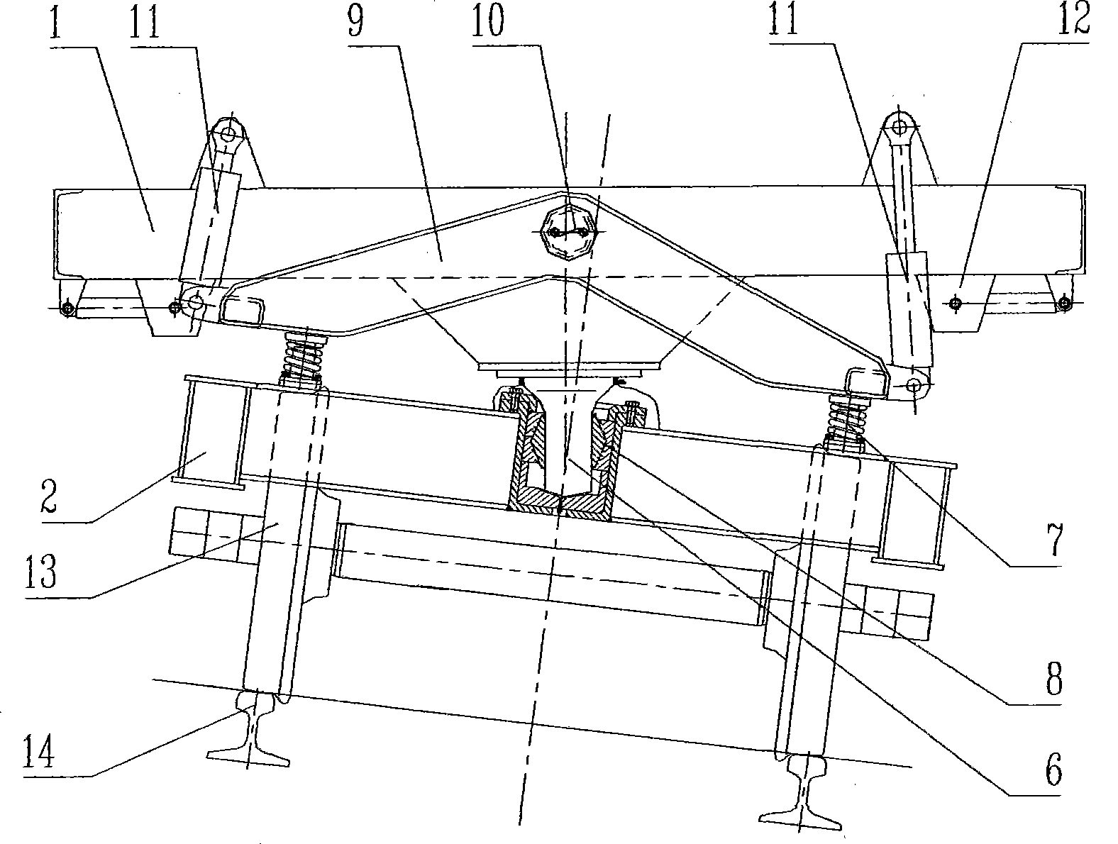
[0024] image 3 Among them, (1) is the main frame, (2) is the bogie, (6) is the center pin, (7) is the elastic lower side bearing, (8) is the spherical bearing, (9) is the equalizing beam, (10) For rotating shaft, (11) is working cylinder, and working cylinder can adopt hydraulic cylinder or air cylinder, and (12) is mechanical locking device, and (13) is wheel pair, and (14) is steel rail. The bogie ...


PUM


Abstract

The invention relates to a railway mounted machine which comprises a main frame, a bogie, a coupler, and the like. The railway mounted machine is characterized in that a leveling mechanism is installed between the main frame and the bogie, and the leveling mechanism adopts the structure as follows: a centre pin (or a ball center plate) and an elastic bottom side bearing are installed on the bogie; the elastic bottom side bearing rubs and contacts with an equalizing lever; the equalizing lever is installed on the main frame through a rotating axle, and a working cylinder and a mechanical locking device are installed between the equalizing lever and the main frame. Compared with the prior art, the railway mounted machine has the advantages that the deflexion motion of the main frame is realized through the leveling mechanism, the main frame can be actively deflected around the bogie within the vertical surface in the width direction of the vehicle, the deflexion of the vehicle body can be eliminated, the main frame, a cab, a working platform and a lorry loading crane can be adjusted to a horizontal position, and the coupling gear is maintained in the original inclined position so as to ensure the normal coupling with a adjacent vehicle.

Description

Technical field [0001] The invention relates to a railway track running machine. Background technique [0002] When the current railway track machinery is working in a curved section, because the rails on the outside of the line are higher than the rails on the inside (railway term: outer rail superelevation), the car body is deflected, making it difficult for construction workers to stand and the workpiece to be placed unstable. . Contents of the invention [0003] The purpose of the present invention is to provide a railway track machine for eliminating the deflection of the car body in the curved working section. [0004] The technical scheme of the present invention includes main frame, bogie and coupler, etc., and is characterized in that: a leveling mechanism is installed between the main frame and bogie, and the deflection action of the main frame is realized through the leveling mechanism, and the main frame It can deflect left and right around the bogie in a ver...

Claims


Application Information

Patent Timeline
Patent Type & Authority Applications(China)
IPC IPC(8): B61F5/38
Inventor 韩高月杨林勇刘旭张来京易红
Owner GEMAC ENG MACHINERY
Learn More