Traction device for spinning machine

A technology of drafting device and spinning machine, applied in spinning machine, continuous winding spinning machine, drafting equipment, etc., can solve the problem of applying difficult thread fastening parts, and achieve the effect of eliminating deflection

Active Publication Date: 2019-03-05
TOYOTA IND CORP
View PDF8 Cites 0 Cited by
  • Summary
  • Abstract
  • Description
  • Claims
  • Application Information

AI Technical Summary

Problems solved by technology

However, since the work of removing the runout at the free end is controlled by extremely small force adjustments, there is a problem that it is

Method used


Image

  • Traction device for spinning machine
  • Traction device for spinning machine
  • Traction device for spinning machine

Examples


Example Embodiment

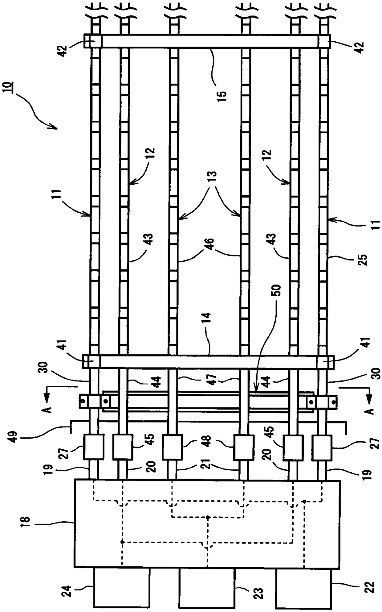
[0029] Hereinafter, a draft device of a spinning machine according to an embodiment will be described with reference to the drawings. In this embodiment, a draft device of a ring spinning machine as a spinning machine will be described. The drafting device according to the present invention is provided with a pair of left and right along the longitudinal direction of the frame of the ring spinning frame, and has a three-wire structure with three drafting rollers.

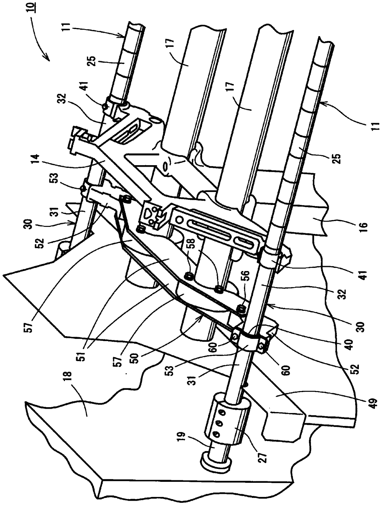
[0030] Such as figure 1 As shown, the drafting device 10 includes a front bottom roller 11, a middle bottom roller 12 and a rear bottom roller 13. The front bottom roller 11, the middle bottom roller 12 and the rear bottom roller 13 are equivalent to drafting rollers. The draft device 10 includes roller seats 14 and 15 that support draft rollers.

[0031] The roller seats 14, 15 support the front bottom roller 11 from below. The roller seat 14 supports a portion of the front bottom roller 11 near one end, and the rol...


PUM


Abstract

A traction device for a spinning machine that easily eliminates the skew of a threaded fastening portion between a line shaft and an end shaft is provided. The traction device of the spinning machinecomprises: a drafting roller having the line shaft (25) and the end shaft (30), the end shaft (30) being screwed to the line shaft (25); a roller seat ( 14) supporting the drafting roller from below;and a drive shaft (19) whose output drives the rotational force of the motor and is coupled to the end shaft (30) by means of a coupling (27). The traction device of the spinning machine has a bearing(40) which is fixed to an intermediate portion of the end shaft (30); and a bracket (50) supporting the bearing (40) at least from below.

Description

technical field [0001] The invention relates to a drafting device of a spinning machine. Background technique [0002] As a prior art of a draft device for a spinning machine, for example, a draft device for a spinning machine disclosed in Patent Document 1 is known. The drafting device of the spinning machine drives the bottom front roller, the bottom middle roller, and the bottom rear roller with two drive motors for the front rollers, two drive motors for the middle rollers, and two drive motors for the rear rollers, respectively. [0003] E.g, Image 6 The illustrated draft device 70 includes a front bottom roller 71, a middle bottom roller 72, and a rear bottom roller 73 as draft rollers. Front bottom roller 71, middle bottom roller 72, rear bottom roller 73 are supported by roller seats 74,75 respectively. In the axial direction of the front bottom roller 71 , a gear mechanism 76 is provided so as to face one roller holder 74 . The gear mechanism 76 is provided with...

Claims


Application Information

Patent Timeline
IPC IPC(8): D01H5/22D01H5/74D01H1/22
CPCD01H1/22D01H5/22D01H5/74
Inventor 三塚尚之佐野彰俊藤井能理
Owner TOYOTA IND CORP
Why Eureka
Try Eureka