Weight solving method for stable wave beam synthesizer

A beamforming and weighting technology, applied in the field of robust beamformer weights solution, can solve problems such as adding constraints, increasing computational complexity in weight vector calculation, and achieving the effects of simple weight solution and increased null width.

Inactive Publication Date: 2009-07-15
CHONGQING UNIV
View PDF0 Cites 14 Cited by
  • Summary
  • Abstract
  • Description
  • Claims
  • Application Information

AI Technical Summary

Problems solved by technology

These methods can achieve good error correction effects, but due to the addition of a large number of constraints, the calculation of the weight vector increases a very large amount of computation

Method used


Image

  • Weight solving method for stable wave beam synthesizer
  • Weight solving method for stable wave beam synthesizer
  • Weight solving method for stable wave beam synthesizer

Examples


Embodiment Construction

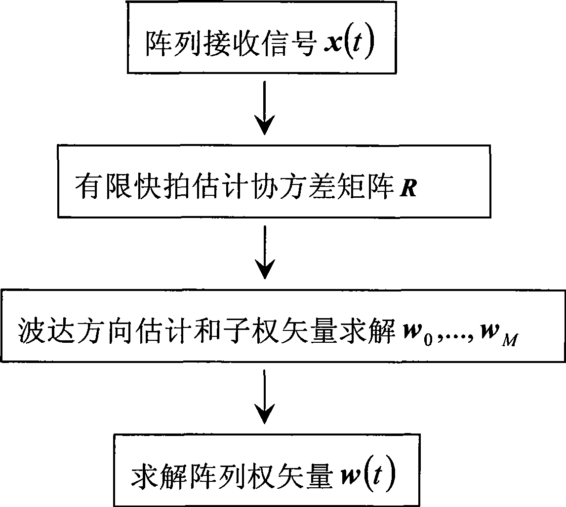
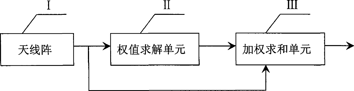
[0012] The method implementation steps are as follows figure 1 shown. System structure such as figure 2 As shown, the beamformer includes an antenna array unit (I), a weight calculation unit (II) and a weighted summation unit (III).

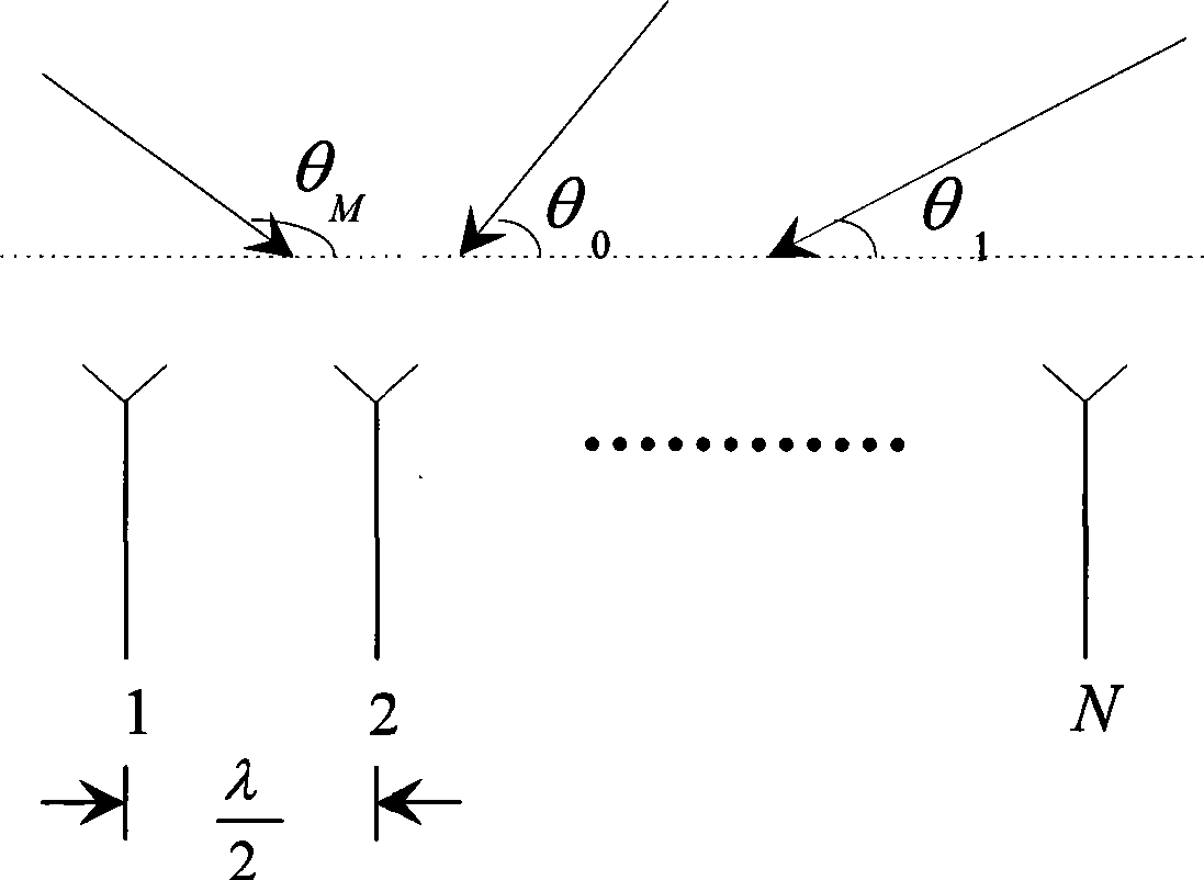
[0013] Such as image 3 As shown in , it is assumed that the array antenna is a uniform linear array, the distance between the array elements is half of the carrier wavelength, and the space has a desired signal s 0 (t), direction of arrival θ 0 , the M interfering signals are respectively s 1 (t),...,s M (t), and the direction of arrival is θ 1 ,...,θ M , these signals are far-field narrowband incoherent signals. The array received signal vector can be expressed as x ( t ) = Σ m = 0 M s m ( t ) ...


PUM


Abstract

The invention discloses a steady beam synthesizer weight solving method comprising the steps: firstly performing an AD sampling to an array receiving signal x(t), estimating a covariance matrix R; secondly performing a direction of arrival estimation through the covariance matrix, and obtaining a desired signal and a direction of arrival of M interface signals; thirdly obtaining M+1 sub weight vectors w0,..., wM; fourthly obtaining a total weight vector of the array according to a formula of w(t)=w0-sigma wm. The steady beam synthesizer has advantages that the array error is not needed to be complexly corrected by increasing constraint conditions, thereby at the same time of having less operation, realizing the robustness of the beam synthesizer.

Description

technical field [0001] The invention relates to the field of beam synthesis, in particular to a method for solving the weight value of a robust beam synthesizer. technical background [0002] The beamformer is widely used in communication and radar. Through a certain optimization method, the received signal x(t) of the array antenna is processed, and the weight vector w(t) of the array is calculated, so that the main lobe of the array pattern is opposite to The quasi-desired signal, while the null trap is aimed at the interference signal, so as to suppress the interference and improve the system output signal-to-interference-noise ratio. However, due to the existence of array position errors, channel inconsistency errors, and array element coupling errors, there are errors in estimating the direction of arrival of signals. As a result of the error, the desired signal is not within the range of the main lobe of the pattern, and the interference is not within the null range o...

Claims


Application Information

Patent Timeline
Patent Type & Authority Applications(China)
IPC IPC(8): H01Q23/00H01Q21/00G06F17/16G01S7/285
Inventor 曾浩张雷刘玲刘晓明
Owner CHONGQING UNIV
Why Eureka
Try Eureka